


Overview
FX-DS110-APL
6
2. Overview
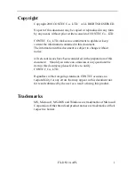
Component Locations
POWER
WRX
WLINK
LINK
RX
Front
DC/UTP
UTP
Side
Ventilation Slits
DIP switches
UTP connector
Power supply switch
Ground
terminal
Power
supply plug
LED
Caution
Do not obstruct the ventilation slots.
This can cause heat buildup which can lead to damage or failure.
Figure 2.1. Component Locations
LED Indicators
The five LED indicators indicate the sending /receiving status of
the wireless or wired LAN, power supply, LAN connection status,
etc.
DIP Switches
The DIP switches are used for initialization, unit type selection, and
operating mode selection.
Power Supply Switch
Selects power supply from the AC adapter, or a UTP cable (requires
the POW-CB10, sold separately).
Summary of Contents for FX-DS110-APL
Page 8: ...FX DS110 APL viii...
Page 19: ...Overview FX DS110 APL 11...
Page 23: ...Operating Mode Descriptions FX DS110 APL 15...
Page 53: ...Spanning Tree Algorithms STA FX DS110 APL 45...
Page 61: ...Troubleshooting FX DS110 APL 53...
Page 69: ...A 46 500 LZV6181 010509...