


Betriebsanleitung / Manual CT 200
- 9 -
© CONTEC
®
2022
CONTEC
Maschinenbau
& Entwicklungstechnik GmbH
Hauptstrasse 146, 57518 Alsdorf (Sieg) / Germany
Tel: +49 (0) 2741 9344-0 Fax: +49 (0) 2741 9344-29
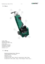
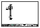
zum Boden verlieren. Lösen Sie die
Klemmschraube der Exzenterachse. Auf der
äußeren Seite des Hinterrades befindet sich
eine Schraube, mit der das Rad auf der Welle
gehalten wird. Durch drehen der Schraube
wird sich auch die Exzenterachse drehen und
die Fräsmaschine sich auf- und wieder
abbewegen. Um ein Lösen der Schraube zu
verhindern,
drehen
Sie
immer
in
Uhrzeigerrichtung. Drehen Sie so lange an der
Welle
bis
sich
die
Werkzeuge
der
Frästrommel alle mit dem gleichen Abstand
zum Boden befinden. Ziehen Sie die
Klemmschraube der Exzenterachse wieder
an.
floor. Loosen the clamping screw of the
eccentric shaft. On the other side of the rear
wheel is a screw which keeps the wheel on the
shaft. Turning the screw will also turn the
eccentric shaft. The floor planer moves up and
down on one side. Always turn the screw
clockwise. Anticlockwise would loosens the
screw. Keep turning until all the tools on the
drum are the same distance to the floor.
Tighten the clamping screw again.
9. Wartung und Reinigung
9. Maintenance and cleaning
9.1
Lager
Alle Kugellager sind auf Lebensdauer
geschmiert.
9.2
Gelenke und Höhenverstellung
Alle Gelenke sind periodisch mit
handelsüblichem Maschinenfett zu
schmieren.
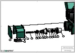
9.3
Riementrieb
Die Riemen sind in Intervallen von ungefähr
30 Betriebsstunden zu überprüfen und ggf.
auszuwechseln. Die Riemenspannung erfolgt
über Anhebung der Motorhalteplatte. Dazu
müssen die 4 M10er Schrauben der
Halteplatte gelöst werden. Die vorderen
Schrauben
sind
in
einem
Langloch
angebracht.
Durch
Anheben
der
Motorhalteplatte
mittels
der
M12
Augenschraube werden die Riemen gespannt.
Danach müssen die Schrauben wieder fest
angezogen werden.
9.4
Reinigung
Eine regelmäßige Reinigung der Maschine
erhöht
die
Lebensdauer
aller
Maschinenkomponenten und Werkzeuge.
9.1
Bearings
All bearings are greased for their life time.
9.2
Height adjustment and joints
All joints have to be greased periodically
with a standard machine grease.
9.3
Belt drive
Check the belts after approximately every 30
hours of operation. To tension the belt you
need to raise the motor bracket. Loosen the 4
M10 screws of the bracket. The front screws
are in two slots. Raise the bracket using the
eyebolt until the belts are tensioned. Tighten
the screws again.
9.4
Cleaning
Regular cleaning of the machine increases
the life of all components and tools of the
planer.
Summary of Contents for CT 200
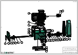
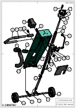
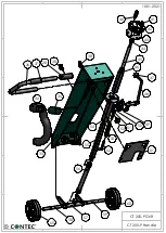
Page 17: ...CT 200 Edger CT 200 Kantenfräse 10 01 2022 72 73 74 61 62 63 4 4 4 3 3 65 67 62 63 69 71 ...
Page 18: ......
Page 19: ......
Page 20: ......