


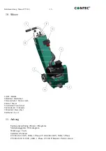


Bodenfräse
Floor Planer
CT 200
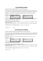
EG-Konformitätserklärung
gemäß der EG-Maschinen-Richtlinie 2006/42/EG vom 17. Mai 2006, Anhang II A
Hiermit erklären wir, dass die nachstehend bezeichnete Maschine in ihrer Konzeption und Bauart sowie in der von uns in
Verkehr gebrachten Ausführung den grundlegenden Sicherheits- und Gesundheitsanforderungen der EG-Richtlinie 2006/42
EG entspricht. Bei einer mit uns nicht abgestimmten Änderung der Maschine verliert diese Erklärung ihre Gültigkeit.
Hersteller:
Contec Maschinenbau & Entwicklungstechnik GmbH, Hauptstraße 146, 57518 Alsdorf, Deutschland
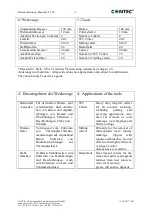
Beschreibung und Identifizierung der Maschine:
Bezeichnung:
Modell:
Seriennummer:
Baujahr:
Es wird die Übereinstimmung mit weiteren, ebenfalls für das Produkt geltenden Richtlinien/Bestimmungen erklärt:
EMV-Richtlinie (2004/108/EG) vom 15. Dezember 2004
Angewandte harmonisierte Normen insbesondere:
DIN EN 12100 Sicherheit von Maschinen – Grundbegriffe, allgemeine Gestaltungsleitsätze, : Grundsätzliche Terminologie,
Methodik, Risikobeurteilung
DIN EN 60204-1 Sicherheit von Maschinen – Elektrische Ausrüstungen von Maschinen, Teil1: Allgemeine Anforderungen
Bevollmächtigter für die technische Dokumentation:
Johannes Greb, Technische Leitung
Alsdorf, 05.03.18
EC-Declaration of Conformity
In accordance with the EEC Machine Directive 2006/42/EG of 17 May 2006, Appendix II A
We hereby certify that the following described machine in its conception, construction and form put by us into circulation is
in accordance with all the relevant essential health and safety requirements of the EC Machinery Directive 2006/42/EEC as
amended and the national laws and regulations adopting this directive. This declaration is no longer valid if the machine is
modified without our consent.
Manufacturer:
Contec Maschinenbau & Entwicklungstechnik GmbH, Hauptstraße 146, 57518 Alsdorf, Germany
Description of the machine:
Function:
Model:
Serial number:
Year:
The agreement with further valid guidelines/regulations following for the products is explained:
EMV-Richtlinie (2004/108/EG) of 15. December 2004
Other applied harmonized standards and specifications in particular:
DIN EN 12100 Sicherheit von Maschinen – Grundbegriffe, allgemeine Gestaltungsleitsätze, : Grundsätzliche Terminologie,
Methodik, Risikobeurteilung
DIN EN 60204-1 Sicherheit von Maschinen – Elektrische Ausrüstungen von Maschinen, Teil1: Allgemeine Anforderungen
Authorized person for the technical documentation:
Johannes Greb, Technical Manager
Alsdorf, 05.03.18
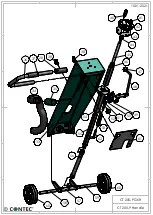
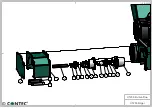
CT 200
Summary of Contents for CT 200
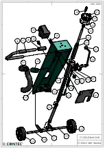
Page 17: ...CT 200 Edger CT 200 Kantenfräse 10 01 2022 72 73 74 61 62 63 4 4 4 3 3 65 67 62 63 69 71 ...
Page 18: ......
Page 19: ......
Page 20: ......