


Betriebsanleitung / Manual CT 200
- 6 -
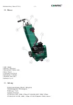
© CONTEC
®
2022
CONTEC
Maschinenbau
& Entwicklungstechnik GmbH
Hauptstrasse 146, 57518 Alsdorf (Sieg) / Germany
Tel: +49 (0) 2741 9344-0 Fax: +49 (0) 2741 9344-29
5. Sicherheitsregeln für den
Betrieb der Bodenfräsen
5. Safety rules
Achtung!
Die Bodenfräse CT 200 ist unter
Berücksichtigung
geltender
Sicherheitsstandards entwickelt worden. Die
technischen Sicherheitsvorkehrungen dürfen
auf keinen Fall entfernt oder verändert
werden. Beim Betrieb der Fräsen sollten
außerdem folgende Punkte beachtet werden:
Attention!
The CT 200 floor planers are
constructed according to existing safety rules
and regulations. These technical precautions
should not be removed or changed under any
circumstances. While operating the machines
the following points should also be kept in
mind:
1.
Die Bodenfräsen dürfen nur mit
sämtlichen Schutzvorrichtungen
betrieben werden.
2.
Der Maschinist darf sich während des
Betriebs nicht von der Bodenfräse
entfernen
3.
Vor dem Verlassen der Bodenfräse hat der
Maschinist den Antrieb stillzusetzen und
das Gerät gegen ungewollte Bewegungen
zu sichern. Bei Elektroantrieben muss
außerdem
der Netzstecker
gezogen
werden.
4.
Nach Wartungs- und Instandsetzungs-
arbeiten müssen die Schutzvorrichtungen
wieder
ordnungsgemäß
angebracht
werden.
5.
Bei Schallpegeln über 90 dB(A) müssen
Schallschutzmittel vom Maschinisten
getragen werden.
1.
The planers should always be operated
with all safety covers and technical
precautions.
2.
The operator should never leave the
machine during operation.
3.
Before leaving the machine all rotary parts
should be brought to a standstill. The
electric models must be disconnected from
the mains. Make sure that the machine
cannot roll or move by itself.
4.
After maintenance and adjustment all
safety covers must be reattached.
5.
If the noise level exceeds 90 dB(A) ear
protectors must be worn.
Bei
größerer
Staubentwicklung
in
geschlossenen Räumen muss die Bodenfräse
mit einer Absauganlage betrieben werden.
In the event of a large amount of dust
during operation connect a dust collector
to the planer.
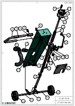
6. Inbetriebnahme und Fräsen
6. Operating
Nach Montage der für die Anwendung
erforderlichen Werkzeuge kann mit dem
Arbeiten begonnen werden.
Motor einschalten.
After mounting the appropriate tools the
operation of the planer can begin.
Turn on the engine.
Die Fräse mit dem Hebel auf Arbeitsstellung
absenken. Die Arbeitstiefe mit dem Handrad
der Höhenregulierung soweit einstellen, bis
die Werkzeuge auf dem Boden greifen und
Lower the planer with the lever to the
operating position. Turn the hand wheel of the
height adjustment until the tools are lowered
to the floor and until you achieve the
Summary of Contents for CT 200
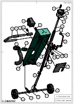
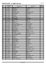
Page 17: ...CT 200 Edger CT 200 Kantenfräse 10 01 2022 72 73 74 61 62 63 4 4 4 3 3 65 67 62 63 69 71 ...
Page 18: ......
Page 19: ......
Page 20: ......