


Betriebsanleitung / Manual CT 200
- 8 -
© CONTEC
®
2022
CONTEC
Maschinenbau
& Entwicklungstechnik GmbH
Hauptstrasse 146, 57518 Alsdorf (Sieg) / Germany
Tel: +49 (0) 2741 9344-0 Fax: +49 (0) 2741 9344-29
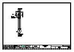
8. Justieren der Frästrommel
8. Adjusting the drum
Durch Unterschiede in den Frästrommeln und
durch Verzug während des Betriebs der Fräse
CT 200 können Fluchtfehler zwischen der
Hinterradachse
und
der
Frästrommelachse auftreten. Dies macht sich
durch
ein
ungleichmäßiges
Fräsbild
bemerkbar. Die Fräse setzt auf einer Seite
früher auf als auf der anderen und nimmt
dadurch mehr Material auf einer Seite ab.
Eines der beiden Hinterräder der CT 200
besitzt
eine
Achse,
die
exzentrisch
ausgebildet ist. (siehe Skizze)
During the operation of the CT 200 floor
planer or after a drum has been changed or
replaced, the drum shaft and the rear wheel
axis can fall out of alignment. This results in
an uneven track on the floor. On one side the
drum touches the floor before the other and
therefore removes more surface material on
this side.
One of the two rear wheels is mounted on an
eccentric shaft (see diagram).
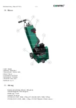
1 Hinterradschwinge
2 Exzenterachse
3 Klemmschraube
4 Schraube
1 Rear wheel swing
2 Eccentric shaft
3 Clamping screw
4 Screw
Falls das Fräsbild eingestellt werden muss,
gehen Sie wie folgt vor: Fahren Sie die
Fräsmaschine auf eine ebene Fläche. Drehen
Sie die Maschine mittels des Handrades so
weit hoch, bis alle Werkzeuge den Kontakt
If the drum has to be adjusted proceed as
follows:
Place the planer on an even floor. Lift the
machine with the height adjustment hand
wheel, until all the tools are well clear of the
Summary of Contents for CT 200
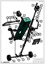
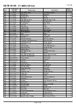
Page 17: ...CT 200 Edger CT 200 Kantenfräse 10 01 2022 72 73 74 61 62 63 4 4 4 3 3 65 67 62 63 69 71 ...
Page 18: ......
Page 19: ......
Page 20: ......