31
COMUNELLO
®Copyright 2016 - All rights reserved
ENGLISH
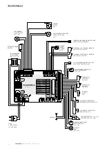
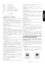
ANT-:
Antenna Ground Input.
ANT+:
Antenna Hot pole input.
CN3:
ENC1 +:
Operator 1 Encoder Power Input
ENC1 E:
Operator 1 Encoder Signal Input
ENC1 GND:
Common GND input
MOT1 FCA:
Operator 1 Opening Limit Switch Input (NC).
MOT1 FCC:
Operator 1 Closing Limit Switch Input (NC).
SYNC D:
Master/Slave Synchronisation Input (Data)
SYNC GND: Master/Slave Synchronisation Input (GND)
CN8:
L:
230 V~ line input (phase).
N:
230 V~ line input (neutral).
• Connection of the Y power cord.
10.3 FUNCTIONAL CHARACTERISTICS
OPERATION:
When either the remote or the low voltage pushbutton panel are used to
control the barrier, operation is as follows:
the first command opens the barrier until motor time elapses or the arm
reaches its opening limit position; the second command closes the barrier;
if another command is transmitted during the Opening movement, the
control unit disregards the command; if a command is transmitted during
the Closing movement the control unit reverses the movement direction.
AUTOMATIC CLOSING:
The control unit can be set up to close the barrier automatically without
sending any additional commands.
Selection of this type of operation is described in Pause time programming
mode.
EMERGENCY STOP INPUT:
The control unit allows the connection of an emergency stop pushbutton
(NC). Pressing this pushbutton irrespective of the current operating mode
of the control unit will cause barrier movements to stop immediately. An
additional barrier movement command will be valid, provided the emergency
stop input is deactivated and, in any case, the control unit will perform the
barrier opening cycle after preflashing for 5 seconds.
Important: in Master/Slave applications, if you want to stop the Barriers
simultaneously, the Emergency Stop Inputs of the Master and Slave control
units must be interconnected.
PHOTOCELLS:
Photocells can be powered by and connected to the control unit in
accordance with directive EN 12453.
• Input DS1 (NC)
Tripping of the photocells during opening is disregarded, while during
closing it causes reversal of the direction of movement.
• Input DS2 (NC)
Tripping during opening causes momentary stopping of the barrier; once
the photocell is freed, the control unit resumes the opening movement.
Tripping during closing causes reversal of the direction of movement.
IMPORTANT:
in Master/Slave applications tripping of input DS2 causes
exclusively reversal of the direction of movement in the closing stroke.
OPENING AND CLOSING LIMIT SWITCHES:
The control unit allows the connection of Opening and Closing limit
switches (NC). Tripping of the limit switches in the associated operating
cycles causes immediate stopping of barrier movement.
ADJUSTMENT OF MOTOR FORCE DURING THE “NORMAL” CYCLE:
The electronic control unit is equipped with a “SPEED” trimmer for
adjustment of Motor Force during the Normal cycle.
Adjustment can be performed in a range of between 50% and 100% of
maximum force during the Normal cycle.
ADJUSTMENT OF MOTOR FORCE DURING THE “SLOWDOWN”
CYCLE:
The electronic control unit is equipped with a “SLOWING” trimmer
adjustment of Motor Force during the Slowdown cycle.
Adjustment can be performed in a range of between 50% and 100% of
maximum force during the Slowdown cycle.
OBSTACLE DETECTION:
The electronic control unit is equipped with a “SENS” trimmer, completely
managed by the microprocessor, for adjustment of the opposing Force
required to detect the presence of an obstacle.
The adjustment can be made with a trip time from a minimum of 0.1
seconds to a maximum of 1 seconds
IMPORTANT:
detection of an obstacle always causes a reversal of the
direction of movement.
MOTOR ENCODER:
The control unit allows connection of an Encoder. The use of Encoders
facilitates the work of the control unit in the Obstacles Detection function
and ensures enhanced precision during execution of arm movements.
FLASHING LIGHT:
The control unit features an output to control a 24 V 25W max flashing
light. Operation of the flashing light depends on the movement of the motor
and automatic closing, which, if selected, enables the flashing light also
during the pause time.
INDICATOR LIGHT:
The control unit allows a 24 V indicator light to be connected to display
the status of the automation system.
Indicator light off: barrier closed
Indicator light on: barrier open
Indicator light slow blinking: opening movement; rapid blinking: closing
movement.
OPERATION WITH TIMER:
The control unit allows a timer to be connected in place of the open – close
pushbutton.
E.g.: at 08.00 am the timer closes the contact and the control unit
commands an opening movement; at 06.00 pm the timer opens the
contact and the control unit commands a closing movement. From 08.00
am – 06.00 pm at the end of the opening cycle the control unit disables the
flashing light, automatic closing and the remotes.
BUFFER BATTERY:
The control unit is equipped with a built-in 27.4 V battery charger to
keep a full charge on the two 12V batteries connected in series. The
batteries allow the barrier to perform several complete open/close cycles
in emergency mode. The Flashing Light and LED strip output will operate
only for the first 4 seconds of the movement when mains power is absent.
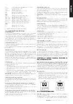
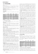
CHECKING THE MOTOR DIRECTION OF RUN
AND MASTER/SLAVE SELECTION
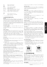
Important Note: make sure the settings of dip-switch SW1 are
changed with the control unit off and then repeat the control unit
programming procedure.
The electronic control unit is equipped with a Dip Switch SW1, which can
be used to change the direction of run of the connected motor without
having to physically alter the electrical connections (DIP 1). In addition, again
using (DIP 2) of Dip Switch SW1, in the case of synchronized operation of
two barriers the control unit can be used to select which one acts as Master
and which one acts as Slave.
Important Note:
• In Master/Slave applications synchronised opening of the barrier is
available using the PUL input or exclusively the master barrier using the
PED input.
• In the Slave control unit all the control and safety inputs (except the
Emergency stop input) are automatically disabled because they are
managed by the control unit configured as the Master.
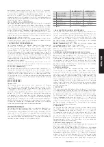
INV
1
ON
2
OFF
MASTER
INV
ON
SLAVE
1
ON
2
SW1
SW1
Summary of Contents for LIMIT 500
Page 3: ...3 COMUNELLO Copyright 2016 All rights reserved FIG 2A FIG 2B FIG 3 FIG 4 FIG 3B FIG 5...
Page 5: ...5 COMUNELLO Copyright 2016 All rights reserved FIG 7A FIG 7B FIG 8A FIG 8C FIG 8B FIG 9A...
Page 7: ...7 COMUNELLO Copyright 2016 All rights reserved FIG 13A FIG 13B FIG 14A FIG 14B...
Page 8: ...8 COMUNELLO Copyright 2016 All rights reserved FIG 16A FIG 16B FIG 15...
Page 9: ...9 COMUNELLO Copyright 2016 All rights reserved FIG 17 FIG 18A FIG 18B...
Page 10: ...10 COMUNELLO Copyright 2016 All rights reserved DEFLECTOR FIXING FIG 20A...
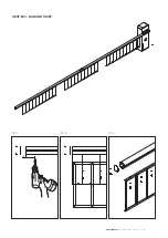
Page 14: ...LIMIT 800 SWING DOWN SUPPORT 45 MIN FIG A FIG C FIG B...
Page 16: ...LIMIT 600 BAR AND SKIRT FIG A FIG C FIG B 110 MIN 110 MIN 200 200...
Page 68: ...NOTES...
Page 69: ...69 COMUNELLO Copyright 2016 All rights reserved NOTES...
Page 70: ...NOTES...
Page 71: ...71 COMUNELLO Copyright 2016 All rights reserved NOTES...

