background image


OMM Series 


User Manual 


Document No.: UM-OPM-2  Rev. A 
File Name:OPM-2 Optical Power Meter User Guide Draft


Confidential


7


Chapter 3


PC Configuration Utility 

3.1


Installation 

1.


Download the Meter Data Manager.msi file from 

www.Comsonics.com

. 

2.


Double-click on the downloaded file to install. 


3.2


Use 

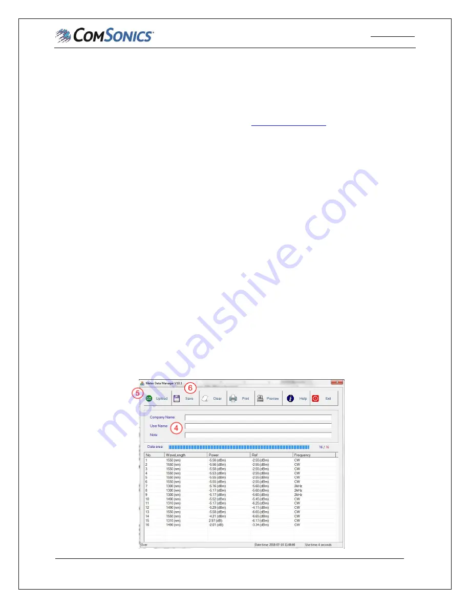
NOTE: Refer to Figure 3-1 in the following steps. 
 

1.


Double-click on the shortcut created during the installation to open the application. 

CAUTION: 

If non-rechargeable batteries are installed in the meter, remove before connecting to PC to 

prevent charging. 

2.


Connect the OMM to the PC using a mini-USB cable and power on. If non-rechargeable batteries 
have been removed, OPM will operate on USB power. NOTE: The first time an OMM series 
meter is connected a USB driver will be installed. 

3.


A USB logo will be displayed on the meter LCD. 

4.


If desired, the company name, user name and notes may be entered in the applicable boxes. This 
information will be linked to measurements transferred to the PC in the following step. It will be 
included in saved data and printed reports. 

5.


Click the “Upload” button to transfer measurements stored in the OPM meter to the PC. 

6.


Click the “Save” button to save the uploaded measurements in a comma separated values (CSV) 
file format. 

7.


Click the “Clear” button to clear measurements from meter. 

8.


Click the “Print” button to print a report of the saved measurements. 

9.


Click the “Preview” button to preview the report of the saved measurements.  

10.


Click the “Help” button to access the softer specific user guide.  

11.


Click the “Exit” button to exit the application.  


Figure 3-1 

Summary of Contents for FHM2A01

Page 1: ...User Manual Optical Multimeter O OM MM M 2 2A A1 1 O OM MM M 2 2B B1 1 O OM MM M 2 2A A2 2 a an nd d O OM MM M 2 2B B2 2 R RE EV V A A J Ju ul ly y 2 20 01 18 8...

Page 2: ...resentation or warranty that using any products in the manner described herein will not infringe any patents of third parties The exclusion of implied warranties may not apply in all cases under some...

Page 3: ...symbol calls your attention to information that if ignored can adversely affect the performance of your ComSonics product or that can make a procedure needlessly difficult LASER DANGER The Laser symbo...

Page 4: ...AND FUNCTION OF COMPONENTS 1 1 1 INVENTORY 1 1 2 FEATURES 1 1 3 DESCRIPTION 1 CHAPTER 2 OPERATION 5 2 1 PERFORM OPTICAL POWER TEST 5 2 2 TWIN MODE 5 2 3 PERFORMING A FIBER LOSS TEST 6 CHAPTER 3 PC CON...

Page 5: ...1 2 Features A High performance Optical Power Meter B Interchangeable connectors C Measures six different wavelengths D Laser light source output on two or three wavelengths E Auto off function saves...

Page 6: ...nt reference setting 3 Modulation Indicator Displays modulated CW signal If none of the tones are shown on the display then they are all off 4 TWIN mode indicator a Single Auto wavelength detection of...

Page 7: ...ta files at once press and hold for 2 seconds The meter must be in the load mode where the stored measurements are shown for this function to work 4 Load key a Short press to enter Load mode Displays...

Page 8: ...hort press until beep sounds to power on with auto off function Active b Long press 2 Seconds after beep when powering on Disables auto off function c Meter will display auto off when function is enab...

Page 9: ...at bottom center of display 8 Turn off the meter 9 Disconnect the tested fiber clean connections and reconnect to fiber network 2 2 TWIN Mode When the ComSonics OLS in the multimeter is paired with a...

Page 10: ...B This provides a Reference level that will allow the power meter to measure signal level differences when measuring fiber loss 2 Repeat these steps for all wavelengths to be tested while ensuring the...

Page 11: ...r NOTE The first time an OMM series meter is connected a USB driver will be installed 3 A USB logo will be displayed on the meter LCD 4 If desired the company name user name and notes may be entered i...

Page 12: ...geable batteries and an AC charging adapter are supplied with the meter The rechargeable batteries may be replaced with standard 1 5 VDC AA batteries To replace the batteries 1 Use a common screwdrive...

Page 13: ...0dBm Measuring Range 70 to 10dBm 50 to 26dBm 70 to 10dBm 50 to 26dBm Laser Source Parameters Output Wavelength 1310 1550nm 1310 1490 1550nm Connector fixed FC PC interchangeable FC SC ST customized Mo...

Reviews: