Appendix - Qualifier System
3-8
Appendix F: Theory of Operation
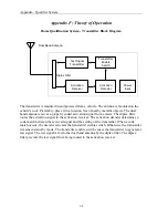
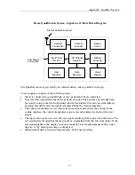
Home Qualification System - Transmitter Block Diagram
The transmitter is mounted in and powered from a vehicle. The antenna is mounted on the
vehicle’s roof. Preferably, place it in a location free of nearby metallic objects. The dual
band antenna receives a properly coded activation signal from a meter. The diplex filter
routes the activation signal to the activation receiver. The activation decoder determines a
code match between the received signal and the setting of the transmitter. When a code
match occurs, the decoder activates the transmitter enable switch. Otherwise, the transmitter
remains in stand-by mode. The transmitter enable switch causes the transmitter to generate a
test signal. The test signal is fed to the dual band antenna by the diplex filter. The diplex
filter prevents the test signal from being routed to the activation receiver.
Activation
Decoder
Activation
Receiver
Test Signal
Transmitter
Transmitter
Enable
Switch
Power
Input
Diplex Filter
Dual Band Antenna
Summary of Contents for CyberTek QUALIFIER
Page 2: ......
Page 8: ...Qualifier System iv This page intentionally left blank...
Page 47: ......
Page 48: ......


