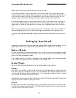
Finally mill 2 small slots and glue the 2 supplied hatch-catches in position against the inside
edges of the plywood stiffening rails (photo P11). Prepare the catches and hatch surface first
by roughing up with coarse sandpaper, fix with one drop of CA to check position, and then
‘trap’ the catches in place with some thick epoxy and milled fibre mix.
Speedbrake
We recommend that you cut out the speedbrake quite
early during the assembly, as it makes access to some
parts and the R/C installation easier through this opening.
Note:
Note that if you decide to use the canards as a
speedbrake (see page 21) you don’t need to install the
speedbrake assembly and can omit this section.
Mark the position of the elastic hinge line using a pin
pushed thru’ the fuselage from the inside. Apply tape to the
bottom of the fuselage and accurately mark the size of the
speedbrake on it, nominally 60mm x 230mm wide. Very
carefully cut out the back edge and sides
only
using a very
sharp knife or a fine razor-saw blade (max. 0.5mm thick).
A piece of double-sided tape applied to the bottom of your
steel straight edge prevents it slipping, and keeps your fin-
gers out of the way of the knife!
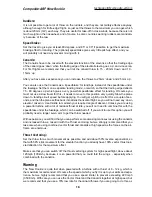
Finally score the front hinge line carefully, just one time,
with the
back
edge of a modelling knife, or a very small tri-
angular needle file (photo P15). This just breaks through the
outer layer of fibreglass cloth (not the hinge tape that is
underneath it) and makes for a much smoother movement
of the elastic hinge - which also puts less load on the
servo. When you have cut it out, the first time you open the
speedbrake it is quite difficult, and you may even hear a
slight ‘cracking’ noise which is just the outer skin (don’t
worry!), but after that it becomes easier.
Sand the edges of the opening and speed brake slightly for
a good fit, with about 0.5 - 0.75mm gap all round. Add
some narrow strips of the 0.8mm plywood supplied around
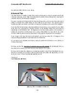
the ends and back to act as a stop for the door, glued in place with thin CA. Fit your servo in
place inside the fuselage, in the milled plywood plate provided, and glue the plate firmly into
the lattice rail on the right side as shown in photo P17. You should use a powerful servo for the
speedbrake control, and we recommend at least 8kg torque. JR8411 shown here.
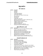
Re-shape the bottom of the phenolic horn as shown in the photo above, scuff up the gluing
surfaces and glue into the 2 small plywood parts with the slots in them. Make sure that the
phenolic horn angles forwards about 45 - 50 degrees to get the necessary throw.
Glue the supplied horn and block onto the inside surface of the speedbrake, exactly in line with
the servo arm, using slow epoxy and milled fibre. Make sure to prepare both surfaces properly
first. Make up the short linkage using the M3 all-thread, locknuts and steel clevises provided
Composite-ARF New Rookie
10
(above) The parts supplied for
speedbrake linkage and servo
mounting.
(above/below) Prepare the bot-
tom of the phenolic horn as
shown, and glue into the 2 slotted
plywood parts securely.


