Vector Thrust System
The hardware for the thrust vectoring system is all included in the kit, and it is your choice if
you want to use it in flight, or not. With it activated you can do all sorts of amazing tumbles and
spins, and of course it also helps in short-takeoff situations. If you do not wish to use the vec-
tor system, then just install the stainless steel tube as described here, and anchor it firmly in
the neutral position to one of the plywood bulkheads or engine mounting rails.
We suggest that you dry-mount your turbine at the same time as installing the vector system,
to check the clearance of the thrust tube to the turbine exhaust nozzle, and adjust the posi-
tions as needed to obtain enough vector throw. Of course the final position of your turbine will
also depend on what type of fuel tank you will use, and whether your turbine has an electric-
starter motor fitted to the front of it. Normally, with an electric-start motor, you will need to
install the turbine as far forward as it will go, with just a few millimetres clearance between it
and the back of the fuel tank.
To get the largest angle available for the thrust vectoring, and therefore the most effect, you
need to mount the vector tube as far back as possible so that it can travel the largest angle
before it touches the turbine exhaust nozzle, or the fuselage. Actually, you can make a small
crescent shaped cut out in the front top and bottom edges of the vector tube to get a little more
clearance and angle if you wish.
Mark the centreline of your turbine on some tape on both the sides of the fuselage, using a
straight edge laid on the mounting brackets (see photo). Bolt the axles onto the thrust tube using
the 2 countersunk M3 bolts from the inside of the tube, with some Loctite. Scuff up all faces of
the 4 phenolic discs, and glue together with thin CA to make 2 pairs. Sand an angle on one face
of each pair of discs to approx. Match the angle of the inside of the fuselage where the axles of
the thrust tube will be positioned. Then, with the phenolic discs on the ends of the axles, trial fit
the thrust tube in the fuselage, with your turbine in place, to check the exact position of the axles
from the back of the fuselage. Normally this is about 20mm.
Drill a 3mm hole in both sides of the fuselage, on the centrelines you marked, for the M3 bolts
that secure the axles. Sand the inside of the fuse where the phenolic discs will be glued, apply
some slow epoxy and milled fibre mixture to the discs, install and bolt in position with the M3
bolts until the glue has cured.
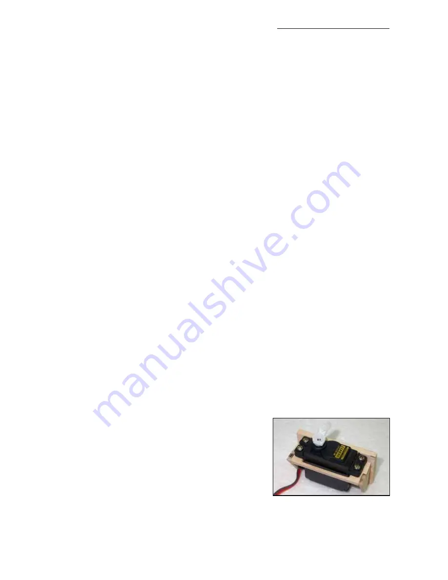
The thrust vectoring system is controlled by a servo that is normally mounted immediately in front
of the rear main bulkhead, glued to the bottom fuselage skin between the main wheel cutouts,
on the milled plywood servo mount supplied in the hardware
pack. Make up the mount in the same way as for the wing
servos. You will need to glue this servo mount onto a 6 -
8mm thick hard balsa or plywood plate to pack it off the fuse-
lage bottom as much as possible (without it touching your
fuel tank), and therefore give you the longest possible servo
arm length for the greatest vector thrust movement. Fit the
servo in place, and glue firmly to the ply bulkhead and bot-
tom fuselage skin with slow epoxy.
Using the long M3 all-threaded rod supplied make up the
linkage to connect it to the vector tube with the steel clevise,
and drill a 6 - 8mm diameter hole thru’ the ply bulkhead just
off-centre so that it will align with the servo arm. Depending
Composite-ARF New Rookie
8
(above) The milled ply servo
mount supplied for the thrust vec-
tor control servo must be glued to
a 6 - 8mm thick balsa plate.


