background image

31 |

P a g e

Edge 540/2.6m

It is important to keep your engine cool, regardless of the engine
manufacturer. Keeping your engine cool is good practice, your
engine will like love for it! Another area you must also consider is
the fuselage. If you are running canisters or tuned pipes this is a

must!

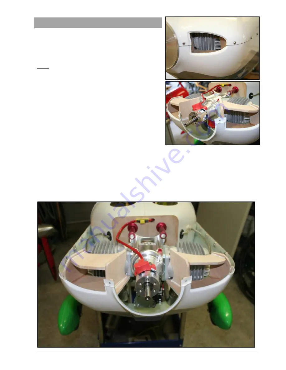
We will show you how we ducted the air to the DA120 that we
used. Clearly with so many engine choices, it would be
impossible to cover all variations. But the principle is the same,
and the following is a good guideline for you to follow.

Remember, what we are trying to achieve, is to channel all the
incoming air from the two openings at the front of the cowl
directly onto the cylinder fins, before it can disburse or be forced
to other areas of the cowl. It’s important that your ducting
components are close to, but not touching your engine. About
2mm is sufficient.

We manufactured our ducting components from 4mm balsa and
0.5mm ply. The balsa is easily shaped to your requirements and is also very light. The ply is added as the top layer
when most of the shaping is done to add strength and a tough surface. Use some card to get the basic shape you
require, and then trace the shape onto the balsa. The thin ply can be easily cut with scissors and the final shape
trimmed with a sanding block. We used medium CA to glue the ply to the balsa.

Tack your components in place with some CA and kicker. Make sure you trial fit as you go. It is also a good idea to
bolt the upper part of the cowl in place from time to time just in case some of the components are getting fowled or
the lower cowl is getting slightly pulled out of shape. When you are satisfied with the fit epoxy the components in
place. While the epoxy is curing, reassemble the cowl and fit to the fuselage, so as everything stays in shape.

Engine cooling and vents

Summary of Contents for Edge 540 2.6m

Page 1: ...E E d d g g e e 5 5 4 4 0 0 2 2 6 6m m A As ss se em mb bl ly y M Ma an nu ua al l...

Page 2: ...their own moulds and pin hinged like the elevator or rudder of our conventional kits The counterbalances emphasize the scale appearance of our Edge and they also decrease the load on the servos The f...

Page 3: ...e assembling your Edge 540 Some of them are common sense but it doesn t hurt to be reminded While you are working with tools and sharp implements be aware of others around you and the environment you...

Page 4: ...d 3d work along with a pretty blistering roll rate But if 3D is your thing and you want all the travel you can get then 1 5 arms can be used but you need to keep in mind that the possibility of high s...

Page 5: ...BLS152 Throttle any good quality servo but make it a good one A good constant idle requires a precise servo such as a JR DS8231 Alloy Servo Arms SWB Secraft Hanger 9 or similar 1 25 1 5 for Elevators...

Page 6: ...be done with a little due care Electric or Battery Drill Pedestal type preferred hand held Drill Bits Various sizes metric Sharp Knife X Acto or similar Measuring Steel rule s tape measure square rul...

Page 7: ...d on either side The T nuts are already pre fitted to the undercarriage mount plate for you at the factory Two bolts are used on each leg and are inserted from the bottom of the fuselage Place some ma...

Page 8: ...n the threaded portion of the T nut or simply let the T nut stand proud inside the wheel pant If you elect to let the T nut stand proud don t forget to fill the space between the T nut and the ply wit...

Page 9: ...m of the fuselage The stern post is 10mm thick mark this area clearly on the bottom of the fuselage The tailwheel mounting plate is approximately 100mm long and is mounted directly in front of the ste...

Page 10: ...fit of both halves mark a line 5mm above the join on the top portion of the cowl The first hole to drill should be the front bolt closest to the spinner Make a mark on the cowl at the centre between t...

Page 11: ...ur centre mark measure 115mm and make a mark Do this on both sides of the centre line Time to drill your holes with a 3mm drill bit Don t forget to drill the hole where you have left the T nut off whe...

Page 12: ...you need to mask off the ply firewall on the fuselage then fit the cowl securely Next we are aiming to image the spinner centre from the cowl onto the firewall To do this we will need a square ruler...

Page 13: ...side pilots view to achieve the correct thrust line If you are using the SWB standoff s this is easy to achieve using the adjustment washers supplied Simply use one large adjustment washer per LH stan...

Page 14: ...ther side of the seam uncut Use the engine dome centre seam line as a reference for marking out the area that requires cutting out As you can see from the pictures we removed an area 80mm x 70mm This...

Page 15: ...The ply tray needs to be shaped to fit behind the firewall inside the engine dome The tray is shaped like a blunt pyramid and measures 17cm at the front 28cm at the rear and is 10cm deep These measure...

Page 16: ...ide the engine dome tack it in place with CA and kicker Make sure you are satisfied with the position of everything and that the throttle servo is correctly placed When you are fully satisfied epoxy i...

Page 17: ...ou will find 2 9mm x 13mm pan head sheet metal screw to mount your servos It s important that you do not use the mounting screws supplied with your servo The mounting rib that is pre installed in the...

Page 18: ...quired Alternatively you may want to use an aftermarket turnbuckle such as those provided by SWB Secraft or Hanger 9 A turnbuckle length of 50mm 2 is required A suitable ball link may also be used in...

Page 19: ...he protective coating of the unprotected extension lead Rubber grommets are readily available from most good hardware stores Select a grommet that is large enough to allow the lead ends to squeeze thr...

Page 20: ...ad into the elevators balance tab This is a simple procedure and will not detract from the performance of your model Use the same procedure used when assembling the elevators However there is an incre...

Page 21: ...tty cheap and can be attached with some 3mm screws and nylock nuts Most hobby stores will keep these items The same measuring process as with the ply mounts applies Work toward keeping the servo outpu...

Page 22: ...g the old one is pretty straight forward The clear canopy needs to be trimmed first Start by removing the excess material so you can fit it over the canopy frame for marking The canopy can be cut with...

Page 23: ...it A syringe is one of the easiest ways of applying the silicon between the canopy and frame A 30ml syringe has more volume than required but its physical size makes it easier to handle it s great fo...

Page 24: ...e required to be mounted onto alloy servo discs DO NOT USE THE STD NYLON SERVO DISCS The standard discs provided with the servos may strip under heavy loads resulting in control surface flutter Screws...

Page 25: ...s to you desired position Everything is now ready for the pull pull cables to be measured up and fitted As mentioned before we used straight cables rather than crossed Crossing the cables will move th...

Page 26: ...r end of the string over the servo mark Tension the string so there is no sag then hold in place with some masking tape You have just established your horizontal cable line Place some masking tape on...

Page 27: ...ic servo arm provided in the hardware pack you can simply loop the cable through the slot in the arm and crimp If you elect to use an alloy arm you can repeat the same process as you have already comp...

Page 28: ...ates Ensure you fit these T nuts underneath the top plates and before you permanently glue the assembly Tack the saddle together with some CA and trial fit on the wing tube socket It s a good idea to...

Page 29: ...ll be glued Also make sure you have the saddle in the correct orientation When you are satisfied with the position use some CA and kicker to tack the saddle to the wing tube socket Apply some epoxy to...

Page 30: ...e this area we will leave up to you Given the wide variation of equipment available and the personal preferences of the end user covering all possible scenarios would be difficult As an example all of...

Page 31: ...not touching your engine About 2mm is sufficient We manufactured our ducting components from 4mm balsa and 0 5mm ply The balsa is easily shaped to your requirements and is also very light The ply is...

Page 32: ...components used But as you can see from the picture there is ample room for a sufficient number of ventilation slots Keep in mind that you should not cut through the seam line or the fibreglass reinfo...

Page 33: ...s carefully lift the model at the C of G points you have measured Control throws This is another area where your personal preferences are going to determine what you actually need We have listed below...

Page 34: ...m either side of the seam line The size of the access holes hole should be no greater than 80mm We hope you have enjoyed assembling your Composite Arf Edge 540 and you have many years of happy flying...

Reviews: