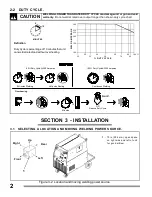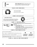
FIGURE 4-10. SPOT TIME CONTROL
FUNCTION SELECTOR:
Place the switch in the position ( I ) activate the function:
1.- Dotting: Welding by time intervals, the duration of each interval (from when the torch trigger
is pressed) will depend on the position pre-set in the control of the spot time.
SPOT TIME CONTROL. This control allows you to adjust the tapping time (duration of
the operation or welding interval) from 0.5 to 4 seconds. Turning the knob clockwise
increases the time. The scale of the control is calibrated in percentage and does not
indicate the interval time.
Install and
connect the
equipment
Turn On Wire feeder
and Power Source
Put On
sa fety
equipment
Install and
prepare Flux
system
Install and
prepare
wire feeder
Set Control
Turn On Flux
system
Beging welding
Readjsut
controls and
begin welding
O pen
gas
valve
Turn On Wire
feeder and Power
Source
Put On
sa fety
equipment
Install and
prepare
wire feeder
Install and
connect the
equipment
Readjsut
controls and
begin welding
Put On
sa fety
equipment
Install and
prepare
wire feeder
Install and
connect the
equipment
Turn On Wire
feeder and Power
Source
Set Controls
Put On
sa fety
equipment.
Select
coa t
electrode
Connect
compreser air
system
Inssert electrode into
tor ch
Supply
compresed air
Turn On Power
Source
Start cutting or
gouging
Install and
connect the
equipment
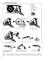
AIR CUTTING AND GOUGING PROCESS (CAC-A)
9
FIGURE 4-11 OPERATION SEQUENCE FOR GMAW, FCAW, SAW, CAC-A
SUBMERGED ARC PROCESS (SAW)
FLUX CORED ARC WELDING PROCESS (FCAW)
SOLID WIRE PROCESS (GMAW)

