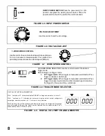
FIGURE 4-7 WIRE SPEED CONTROL
1.- WIRE SPEED CONTROL.
Use this control to select wire feed speed in speed ranges.
Turn in clock wise to increase speed. The numbers is a
percentage respect a maximun rated speed (900ipm)
1
FIGURE 4-8 TRIGGER MODE SELECTOR.
TRIGGER MODE SELECTOR.Use this control to select the desired
trigger mode.
Select always one trigger mode:
1.
2T Trigger mode
: When trigger is depressed, weld starts. When
trigger is released, weld stops.
2.
4T Trigger mode
: When trigger is depressed, weld starts. When
trigger is released, weld remains. After depressing and releasing
the trigger for the second time, weld stops.
TRIGGER
FIGURE 4-9. DIGITAL VOLTMETER AND AMMETER
DIGITAL VOLTMETER AND AMMETER.
W ith "contactor off". Voltmeter display PRESET voltage and ammeter is turn off.
W ith "contactor on". Voltmeter and ammeter display actual output voltage and
amperage, ammeter remains off if current is zero amperes.
W hile welding, the meters measure and display the output arc voltage and amperage.
once extinguished the arc, the digital meters retained the arc values approx 4 sec.,
subsequently shown PRESET value.
VOLTAGE ADJUSTMENT
Use this control to set the arc voltage.
FIGURE 4-5 INPUT POWER SWITCH
INPUT POWER SWITCH.
Place the power switch in ON
position energizes the welding power source. Place the
power switch in the OFF position the unit shuts down.
V
8
FIGURE 4-6 VOLTAGE ADJUST

