Compaq Prolinea 4100 Maintenance & Serice Manual Download Page 109

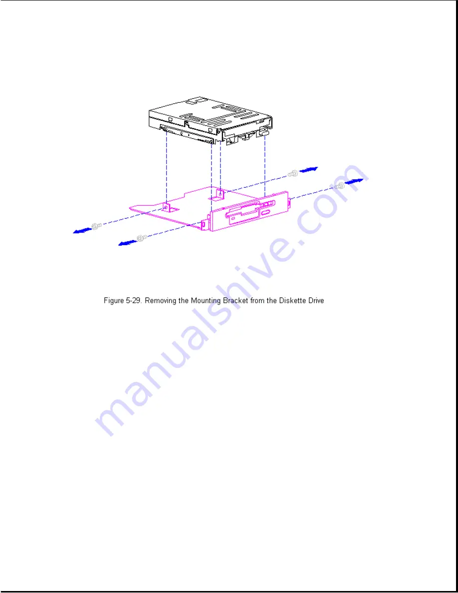
Reverse the above procedure to install the mounting bracket and bezel onto
the diskette drive and install the diskette drive.

Second Hard Drive

Hard drives installed in the ProLinea Personal Computer use cable-select
technology.

Cable-select technology identifies the hard drives as device

0 (master) or device 1 (slave), depending on where they are connected on
the cable-select cable. The configuration jumpers on both hard drives are
set the same; the jumpers are preset for cable-select installation.

A typical cable-select installation is illustrated in Figure 5-30. The
single-port hard drive cable connects the cable-select cable to the
backplane board. The device 0 drive is the drive that is closer to the
backplane board; it is connected to the short segment of the cable-select
cable. The other drive is identified as the device 1 drive by being
connected to the longer segment of the cable-select cable.

IMPORTANT: Cable-select may not function properly if drives other than

those supported by Compaq are installed.

NOTE: The second drive on a cable-select cable can be a CD-ROM drive.

However the CD-ROM drive must be installed in the device 1 position
if there is a hard drive installed on the same cable.

Ensure that

the CD-ROM drive is set for cable-select configuration.

Summary of Contents for Prolinea 4100

Page 1: ...Thank you for purchasing this Factory Service Manual CD DVD from servicemanuals4u com Please check out our eBay auctions for more great deals on Factory Service Manuals servicemanuals4u...

Page 2: ...U S A Compaq Deskpro LTE Contura Registered U S Patent and Trademark Office ProLinea is a trademark of Compaq Computer Corporation Microsoft and MS DOS are registered trademarks of Microsoft Corporati...

Page 3: ...esult in damage to equipment or loss of data IMPORTANT Text set off in this manner presents clarifying information or specific instructions NOTE Text set off in this manner presents commentary sidelig...

Page 4: ...e front and below the top expansion slot on the rear of the computer Locating Additional Information The following documentation is available to support the Compaq ProLinea Family of Personal Computer...

Page 5: ...Family of Personal Computers introduces a new generation of desktop computers designed for the business environment The family includes Desktop 3 slot 3 bay DT3 and Desktop 4 slot 4 bay DT4 models Thi...

Page 6: ...in Table 1 1 These desktop computers have two ISA expansion slots one shared PCI ISA expansion slot one Compaq option slot and three mass storage bays All models include a 3 5 inch diskette drive Tab...

Page 7: ...available in all geographic regions Compaq ProLinea Personal Computer DT4 Models The Compaq ProLinea Personal Computer is available in the DT4 models described in Table 1 2 These desktop computers ha...

Page 8: ...86 75 720 MB 16 MB PCI Local 256 KB No Bus ProLinea 590 586 90 None 8 MB PCI Local 256 KB No Bus ProLinea 590 586 90 420 MB 8 MB PCI Local 256 KB No Bus ProLinea 590 586 90 420 MB 8 MB PCI Local 256 K...

Page 9: ...hird height drive bay one external third height drive bay and two external half height drive bays o CD ROM drive with Enhanced Business Audio on selected models o PCI local bus IDE interface for hard...

Page 10: ...ges to the flash ROM o Keyboard password allows the computer to boot up but prevents data input until the password is entered o Parallel interface control prevents transfer of data through the paralle...

Page 11: ...memory can be upgraded according to the schedule in Table 1 4 Table 1 4 Upgrade Schedule Processor Standard Memory Expandable to SIMM Sockets 486DX2 50 4 MB 128 MB 4 486DX2 50 8 MB 136 MB 4 486DX2 66...

Page 12: ...20 250 MB tape drive with compression o 340 680 MB tape drive o 525 MB tape drive o 1 2 GB ACA tape drive o 2 8 GB Turbo DAT tape drive o Internal Quad Speed IDE CD ROM drive Monitor Options The follo...

Page 13: ...ory module for QVision 2000 Graphics Controller Serial Parallel Interface Board Ther serial parallel board option is available from Compaq for the ProLinea Family of Personal Computers This board uses...

Page 14: ...ols and LEDs The front panel controls and LEDs for the DT3 and DT4 are almost identical The controls and LEDs are identified in Figure 1 3 and described in Table 1 5 Table 1 5 Front Panel Controls and...

Page 15: ...will not scroll 6 Diskette Drive Turns on when the diskette drive is reading Activity Light or writing 7 Diskette Eject Button Ejects a loaded diskette 8 Power On Off Switch Turns the computer on and...

Page 16: ...mouse 3 Voltage Select Switch Switches voltage between 115 VAC US and 230 VAC to match geographical requirements 4 Serial Port Connects to serial devices such as a serial printer 5 Parallel Port Conn...

Page 17: ...The system board shares the common backplane board with the expansion cards No mounting screws are used with the system board Expansion boards are installed horizontally above the system board engagin...

Page 18: ...characteristics o Used on 3 slot 3 bay and 4 slot 4 bay computers o Integrated 8 MB RAM on the system board o 4 SIMM sockets for memory expansion o PCI Local Bus integrated graphics controller o Acco...

Page 19: ...ach connector can be individually disabled so that option card IDE interfaces will work Diskette Drive Interface The diskette drive interface is 8477 compatible Serial Port The serial port is RS 232C...

Page 20: ...S with tin lead pins must be used for memory upgrades Cache All of the computers support a second level write back cache 486DX2 XX and 486DX4 100 models support an optional 128 KB or 256 KB cache boar...

Page 21: ...error condition Adherence to the procedures and precautions described in this chapter is essential for proper service Chapter 2 1 Power On Password The power on password prevents use of the computer u...

Page 22: ...st POST is a series of diagnostic tests that runs automatically when the system is turned on POST checks the following assemblies to ensure that the computer system is functioning properly o Keyboard...

Page 23: ...ROM 1 Short placement 2 Verify the correct ROM 3 Replace the ROM 101 I 0 ROM None Option ROM checksum 1 Inspect the ROM Error placement 2 Verify the correct ROM 3 Replace the ROM 102 System None DMA t...

Page 24: ...ory Run the cache controller controller or RAM Configuration Failure failure and Diagnostics Utilities 301 Keyboard None Keyboard Failure Reconnect keyboard Error with computer turned off 301 Keyboard...

Page 25: ...Not Reported In CMOS 703 CMOS Reports 2 Short Configuration error Run Computer Setup a Coprocessor That Has Not Been Detected By POST Message Beeps Probable Cause Recommended Action 1151 COM Port 1 2...

Page 26: ...type Configuration and Diagnostics Utilities 1791 Disk 1 None Hard drive error or Run the Failure wrong drive type Configuration and Diagnostics Utilities XX000Y ZZ Parity None Parity RAM failure Run...

Page 27: ...e by selecting options on a menu called Configuration and Diagnostics To display this menu restart the computer then press the F10 key when the square cursor displays in the upper right corner of the...

Page 28: ...he Power On Self Test POST runs you hear two beeps then the cursor moves to the upper right corner 3 If prompted select the desired language 4 A menu similar to the one shown in Figure 2 2 will be dis...

Page 29: ...tilities group box Once the program is running you can use the tool bar or the menus to browse through the information Some examples of the information you can view are o Product name o CPU informatio...

Page 30: ...ollowing o Date and time o Installed devices o Memory status o Password status o Interface configurations o Graphics configuration o Computer serial number o Controller status The following activities...

Page 31: ...ion checks the following o CPU main system o Keyboard o Pointing device interface o Parallel interfaces o Graphics controllers o Diskette drives o Fixed disks o Serial interfaces o Installed Compaq de...

Page 32: ...mpaq highly recommends that backup diagnostics diskettes are created as soon as the system is configured This software is required to troubleshoot the system if the hard drive cannot be accessed or mu...

Page 33: ...led 107 xx CMOS RAM test failed The following steps apply to 107 xx through 109 xx 108 xx CMOS interrupt test failed 1 Replace the battery clock module and retest 109 xx CMOS clock test 2 Replace the...

Page 34: ...3 Replace the system board and retest 304 xx Failed Keyboard Repeat Test Table 2 5 Parallel Printer Test Error Codes Error Code Description Recommended Action 401 xx Printer failed or The following s...

Page 35: ...onfiguration and Diagnostics Utilities Table 2 7 Serial Test Error Codes Error Code Description Recommended Action 1101 xx Serial port test 1 Check switch settings on the failed Serial Parallel Interf...

Page 36: ...eplace the hard drive controller 1704 xx Hard drive random board and retest if applicable seek test failed 4 Replace the hard drive and retest if applicable 1705 xx Hard drive controller 5 Replace the...

Page 37: ...if applicable and retest failed 5 Replace the tape drive and retest 6 Replace the system board and retest 1905 xx Tape read test failed 1906 xx Tape write read compare test failed Table 2 11 Video Tes...

Page 38: ...codes 2403 xx Video attribute test 1 Run the Configuration and failed Diagnostics Utilities 2 Replace the monitor and retest 2404 xx Video character set 3 Replace the video board and retest test faile...

Page 39: ...C 640 x 350 64 color set test failed 2424 xx ECG VGC monochrome text mode test failed 2425 xx ECG VGC monochrome graphics mode test failed 2431 xx 640 x 480 graphics test failure 2432 xx 320 x 200 gra...

Page 40: ...place the CD and retest 2 Check the jumper settings on the 6600 xx ID test failed adapter board 3 Verify that the speakers are 6605 xx Read test failed connected 4 Check and or replace the power and 6...

Page 41: ...est Names XX00 XX ID XX03 XX Power Check XX05 XX Read XX06 XX SA Media XX08 XX Controller XX23 XX Random Read XX28 XX Media load unload Table 2 15C SCSI Test Error Codes Error Code Description Recomme...

Page 42: ...edia hard error 1 Replace current DATA CD with different DATA CD 2 Replace drive 67XX 24 Media hard error 1 Ensure correct media type for this tape drive 2 Replace current tape with new tape 3 Replace...

Page 43: ...cleaning XXXX 92 Side panel not N A installed XXXX 93 Primary redundant power supply failed alternate supply active XXXX 99 Autoloader reported 1 Install tape s in autoloader tape tapes not loaded dr...

Page 44: ...problems Table 2 16 Solutions for Power Problems Problem Possible Solution Computer will not turn on Ensure that the computer is connected to a power source Computer does not The Real Time Clock RTC b...

Page 45: ...some quick checks for monitor related problems Table 2 18 Solutions for Monitor Problems Problem Possible Solution Characters are dim The brightness control is not set properly Adjust the brightness...

Page 46: ...re are not included When you run the diagnostics the test results are stored in a log After completing the test you can print this log to a local printer or save it to a file Alternatively before runn...

Page 47: ...AUTOFIX to correct the problems If a large number of lost allocation units is found run the MS DOS defragmentation program DEFRAG Type HELP SCANDISK for more information Hard drive activity light The...

Page 48: ...for CD ROM drive problems Table 2 21 Solutions for CD ROM Problems Problem Possible Solution Cannot read compact disc 1 CD is not properly seated in the drive Eject the CD press down on the CD firmly...

Page 49: ...aq ProLinea Family of Personal Computers Spare part numbers and warranty tier are included Chapter 3 1 System Unit Table 3 1 System Unit Spare Parts Spare Part Warranty Description Number Tier 1 Hood...

Page 50: ...Rear corner bezel Quantity 2 k Cable clip l Front corner bezel Quantity 2 m Power switch 172795 001 D 6 Power Supply 145 W US 172765 001 B 6 Power Supply 145 W PFC outside of US 172766 001 B 7 Miscel...

Page 51: ...ive 420 MB IDE w o Bracket 172780 001 B 3 Hard Drive 540 MB IDE w o Bracket 188666 001 B 4 Hard Drive 720 MB IDE w o Bracket 172842 001 B 5 Hard Drive 1 GB IDE w o Bracket 172941 001 B 6 Hard Drive 53...

Page 52: ...8 201 B 2 Diskette Drive 5 25 1 2 MB 1 2 height 141367 201 B 3 CD ROM Drive Internal Quad Speed IDE 172717 001 B 4 Tape Drive 120 250 MB w Compression 187657 001 B 5 Tape Drive 340 680 MB w Compressio...

Page 53: ...able Diskette Drive DT3 172477 001 B 3 Cable Diskette Drive DT4 172797 001 A 4 Power cord AC Gray US Canada Latin America Taiwan Korea Brazil Thailand 121258 001 A 4 Power cord AC Black Australia New...

Page 54: ...SI 3 Connector 146997 001 A 6 Cable hard drive cable select 172945 001 A 7 Cable LED Assembly 172531 001 A 8 Adapter AUI to BNC Ethernet Transceiver not shown 192768 001 A 9 Cable Token Ring not shown...

Page 55: ...MHz 172670 001 A 5 Processor 586 100 MHz 172760 001 A 6 VRAM 2 MB for QVision 2000 Graphics Controller 137895 001 A 7 VRAM 1 MB for QVision 1280 P Graphics Controller 172467 001 A 8 DRAM 1 MB for PCI...

Page 56: ...ystem and Backplane Boards Spare Part Warranty Description Number Tier 1 System Board 586 based PCI Local Bus Integrated Graphics for DT 3 and DT 4 172019 001 A 2 System Board 586 based for use with Q...

Page 57: ...of the system serial number for example XXXXHLH1XXXX where HLH1 is the configuration code Use the configuration code and Table 3 7 or Table 3 8 to find the correct spare part number for a replacement...

Page 58: ...170 001 GLB2 3910 002 172170 001 GLB3 3910 002 172170 001 GLB4 3910 002 172170 001 HLB1 3910 002 172170 001 HLB2 3910 002 172170 001 HLB3 3910 002 172170 001 HLB4 3910 002 172174 001 GLC2 3910 003 172...

Page 59: ...1 GNA2 3816 002 172019 001 GNA3 3816 002 172019 001 GNA4 3819 002 172024 001 GNA5 3816 002 172019 001 HNA1 3816 002 172019 001 HNA2 3816 002 172019 001 HNA3 3816 002 172019 001 HNA4 3819 002 172024 00...

Page 60: ...205 A 12 Keyboard Spacesaver French Canadian 160648 212 A 13 Keyboard Spacesaver German 160648 204 A 14 Keyboard Spacesaver Greek 160648 215 A 15 Keyboard Spacesaver Hungarian 160648 221 A 16 Keyboard...

Page 61: ...Keyboard Spacesaver Taiwanese 160648 234 A 30 Keyboard Spacesaver Turkish 160648 214 A 31 Keyboard Spacesaver UK English 160648 203 A 32 Keyboard Spacesaver US 160648 201 A 33 Keyboard Spacesaver Yugo...

Page 62: ...Color Monitor Low Emissions Energy Saver NH 471P 143805 501 A 3 SVGA 14 Color Monitor Low Emissions Energy Saver SH 471P 143806 501 A 3 SVGA 14 Color Monitor Low Emissions Energy Saver NH 472P 143807...

Page 63: ...or Low Emissions AssetControl GSA 444 147265 604 A 6 171 FS Color Monitor Low Emissions NA 490 190916 001 A 6 171 FS Color Monitor Low Emissions NH 490 190916 002 A Spare Part Warranty Description Num...

Page 64: ...NOTE AssetControl feature is not available on the Compaq ProLinea Personal Computer Chapter 3 7 Miscellaneous Hardware Kit Table 3 11 Miscellaneous Hardware Kit Spare Part Warranty Description Number...

Page 65: ...cket Minitower only not shown 7 3 5 Diskette Hard Drive left rail 8 3 5 Diskette Hard Drive right rail 9 Main panel clip for Minitower not shown 10 Access panel clip for Minitower not shown 11 Drive S...

Page 66: ...795 001 D 2 Drive Cage Lock 3 Switch Holder 4 Switch Cap DT3 DT4 5 Switch cap V3 V4 6 Option Card Guide DT3 7 Option Card Guide DT4 8 System Board Guide DT3 DT4 9 Insulator Strip 10 Cable clip 11 Fron...

Page 67: ...160274 001 A 3 Tape Cartridge 250 MB 115298 001 D 4 Tape Cartridge 525 MB 119504 001 D 5 Option slot cover 173007 001 D 6 DAT Cartridge 2 0 GB Not shown 131148 001 D 7 DDS2 Cartridge 5 0 GB Not shown...

Page 68: ...1FS Monitor 189574 001 D Shipping Box 171FS Monitor Quantity 5 189577 001 D Box and Packing 1024 Monitor 189575 001 D Shipping Box 1024 Monitor Quantity 5 189578 001 D Chapter 3 11 Documentation Spare...

Page 69: ...s 172636 331 D Kit ProLinea Quick Setup Guide Beyond Setup Guide Norwegian 172636 091 D Kit ProLinea Quick Setup Guide Beyond Setup Guide Polish 172636 241 D Spare Part Warranty Description Number Tie...

Page 70: ...Microsoft Windows 3 5 inch Diskette Kit French 133413 051 D Microsoft Windows 3 5 inch Diskette Kit Italian 133413 061 D Microsoft Windows 3 5 inch Diskette Kit Spanish 133413 071 D Microsoft Windows...

Page 71: ...Driver Kit Spanish 133421 071 D Spare Part Warranty Description Number Tier SCO Unix Support Drivers 125873 001 D OS 2 Support Drivers 196004 001 D Windows NT Support Drivers 196012 001 D Flash for Sy...

Page 72: ...33 061 D About Your Computer Korean 181833 AD1 D About Your Computer Latin American Spanish 181833 161 D About Your Computer Netherlands 181833 331 D About Your Computer Norwegian 181833 091 D About Y...

Page 73: ...Table 3 17 QuickFind Part Number Suffix Suffix Month Suffix Month 001 January 007 July 002 February 008 August 003 March 009 September 004 April 010 October 005 May 011 November 006 June 012 December...

Page 74: ...vide some protection but in many cases the discharge contains enough power to alter device parameters or melt silicon junctions Generating Static Table 4 1 shows how different activities generate stat...

Page 75: ...materials must be wired to ground and proper materials selected to avoid static charging When grounding is not possible use an ionizer to dissipate electric charges Preventing Damage to Drives To pre...

Page 76: ...rs and vacuums that are conductive o Use a portable field service kit with a static dissipative vinyl pouch that folds out of a work mat Also use a wrist strap and a ground cord for the work surface G...

Page 77: ...s o Conductive tote boxes o Metal tote boxes o Opaque shielding bags o Transparent metallized shielding bags o Transparent shielding tubes Chapter 4 2 Service Considerations Listed below are some of t...

Page 78: ...e connector Handle cables by the connector whenever possible In all cases avoid bending twisting or tearing the cables and ensure that the cables are routed in such a way that they cannot be caught or...

Page 79: ...The system serial number should be provided to Compaq when requesting information or ordering spare parts The system serial number is displayed in two locations on the right side of the computer near...

Page 80: ...o prepare the computer for the removal and replacement procedures complete the following steps 1 Remove any diskette compact disc or tape from the computer 2 Turn off the computer and any peripheral d...

Page 81: ...ent procedures that do not require access to the internal components of the computer This includes o Compaq Logo o Rear Corner Bezels o Feet o Cable Lock o Unit Cover o Front Bezel o Rear Bezel Compaq...

Page 82: ...he logo is to be installed with a clean damp cloth 4 Remove the protective cover from the back of the replacement logo and press it into place as shown in Figure 5 3 Rear Corner Bezels The rear corner...

Page 83: ...s have to be removed to gain access to the feet The feet have an adhesive surface and are shipped with a protective strip in place If necessary use a small flat bladed screwdriver to remove the old fe...

Page 84: ...Cable Lock Installation The center thumbscrew is the recommended location for installation of the optional cable lock Remove the thumbscrew and install the cable lock U bolt as shown in Figure 5 6...

Page 85: ...described in section 5 3 2 Loosen the three thumbscrews on the rear of the computer to release the cover Figure 5 7 You may need a flat bladed screwdriver to loosen the screws NOTE If the computer has...

Page 86: ...d to the chassis Lifting the computer by using this bracket as a handle results in the system board with bracket attached being removed from the computer To avoid damage to the computer and possible p...

Page 87: ...clips so they can be replaced in their original locations and orientations 4 Reverse steps 1 through 3 to install a front bezel taking care to properly position and orient the grounding clips Rear Be...

Page 88: ...ion 4 If the existing rear bezel is still in place note the locations of the snap action tabs Figure 5 9 and carefully pry the bezel away from the rear panel of the base pan 5 To install a rear bezel...

Page 89: ...y complete the following steps CAUTION Note the orientation and routing of each power supply cable before you disconnect it Damage to the computer can result if the cables are inserted incorrectly 1 C...

Page 90: ...4 Disconnect the power switch Figure 5 11 5 Release the drive cage lock plastic on the top of the drive cage by rotating it clockwise as shown in the top view in the inset in Figure 5 12...

Page 91: ...itch cable clamps on the floor of the chassis Push the metal drive cage release Figure 5 13 away from the drive cage and elevate the back end of the drive cage The drive cage release will engage a cut...

Page 92: ...7 Release the wires going to the power switch from the clamps on the base pan Figure 5 14...

Page 93: ...8 Disconnect the power supply cables from the hard drive Figure 5 15 CD ROM drive Figure 5 16 and diskette drive Figure 5 17 Any other mass storage device will disconnect in the same manner...

Page 94: ......

Page 95: ......

Page 96: ...disengage it from the base pan Then lift it out slightly and disconnect the two power supply cables from the connectors on the backplane board Figure 5 18 These connectors are not the same size so th...

Page 97: ...s on the backplane Figure 5 18 2 Move the power supply into its mounting position making certain that it engages the tabs in the floor of the base pan and install the four power supply mounting screws...

Page 98: ...13 and lower the drive cage to its seated position 7 Install the unit cover assembly Figure 5 7 CAUTION Verify that the power supply voltage select switch is set to the proper voltage before applying...

Page 99: ...emove the switch from the switch holder by spreading the tabs and sliding the switch out of the back of the switch holder It may be necessary to break the tabs to free the switch 7 Reverse the above p...

Page 100: ...tion 1 Complete the steps in Section 5 3 to prepare the computer for disassembly 2 Complete the steps in Section 5 4 to remove the unit cover to gain access to the hard drive 3 Disconnect the power an...

Page 101: ...es on the hard drive bracket engage cutouts in the side of the drive cage Be sure to engage these flanges when installing the hard drive 5 Remove the four screws securing the bracket to the hard drive...

Page 102: ...pe drive or CD ROM drive in the lower drive bay o DT4 has an optional CD ROM drive or tape drive in the upper drive bay a 3 5 inch diskette drive in the middle drive bay and an optional diskette drive...

Page 103: ...computer 2 Insert a small rod or jeweler s screwdriver 1 16 inch 1 4 mm blade into the manual eject hole Figure 5 23 and push firmly to release the tray Note that the manual eject hole is immediately...

Page 104: ...ease Figure 5 13 away from the drive cage and elevate the back end of the drive cage The drive cage release will engage a cutout in the side of the drive cage when the drive cage has been elevated the...

Page 105: ...ive cage down into its normal operating position taking care not to damage the drive cage lock and retainer 7 The CD ROM drive is secured in place with two screws on the front of the computer Remove t...

Page 106: ...astic on the top of the drive cage by rotating it clockwise Figure 5 12 4 Elevating the drive cage will provide access to the drive cable connectors Push the metal drive cage release Figure 5 13 away...

Page 107: ...esting position ensure that none of the cables are pinched between the drive cage and the base pan 6 Lower the drive cage down into its normal operating position taking care not to damage the cables a...

Page 108: ...8 Remove and retain the diskette drive mounting bracket with bezel attached Figure 5 29 The bracket is secured in place with four screws...

Page 109: ...illustrated in Figure 5 30 The single port hard drive cable connects the cable select cable to the backplane board The device 0 drive is the drive that is closer to the backplane board it is connecte...

Page 110: ...plastic on the top of the drive cage by rotating it clockwise Figure 5 12 4 Elevating the drive cage will provide access to the drive cable connectors Push the metal drive cage release Figure 5 13 awa...

Page 111: ...an 6 Lower the drive cage into its normal operating position taking care not to damage the cables or the drive cage locks 7 The hard drive is obstructed from view by a blank bezel The hard drive and b...

Page 112: ...8 Remove and retain the hard drive mounting bracket Figure 5 33...

Page 113: ...installation of the hard drive into an accessible drive bay Drive Bay Bezel To remove a drive bay bezel complete the following steps 1 Complete the steps in Section 5 3 to prepare the computer for dis...

Page 114: ...the mass storage devices from the drive cage To remove and replace the drive cage lock assembly complete the following steps 1 Complete the steps in Section 5 3 to prepare the computer for disassembly...

Page 115: ...ete the steps in Section 5 3 to prepare the computer for disassembly 2 Complete the steps in Unit Cover Removal and Replacement in Section 5 4 to gain access to the speaker NOTE If the Enhanced Busine...

Page 116: ...4 Release the speaker bracket from the front panel by pushing on the tab and rotating the bracket away from the chassis panel Figure 5 37...

Page 117: ...er 5 11 Expansion Cards and Slot Covers The DT3 has three ISA expansion slots one of which is shared for PCI expansion The DT4 has four ISA expansion slots two of which are shared for PCI expansion Ex...

Page 118: ...ngth expansion card from a CDS model the speaker will have to be removed from the front panel of the chassis to provide adequate clearance See Section 5 9 4 Remove the screw securing the expansion car...

Page 119: ...prior to removing the system board The replacement system board is shipped from the factory with the bracket and I O panel installed System Board Removal To remove the system board from the computer c...

Page 120: ...the relationship between the ends of the system board bracket and base pan You can use this as an aid in determining that the board is properly seated at replacement 3 Disconnect any option card cable...

Page 121: ...ttom side Verify that the bumper pads are in place before installing the system board 1 Slide the system board all the way in until it touches the backplane connector 2 It takes a strong push to seat...

Page 122: ...stem board is seated Also the relationship between the ends of the system board bracket and base pan can serve as another indicator that the board is properly seated Chapter 5 13 Option Card The optio...

Page 123: ...Section 5 4 to gain access to the option card 3 Disconnect any cables connected to the option card NOTE It might be necessary to remove expansion card s to have sufficient access for cable removal If...

Page 124: ...lane board Chapter 5 14 LEDs The LEDs are mounted on the front card bracket Figure 5 43 The option cards system board and fax modem card must be removed prior to removing the LEDs To remove the LEDs c...

Page 125: ...ill prevent interference from this cable during these procedures 5 Disconnect the LED cable from its connector on the backplane Figure 5 43 6 Release the card guide from the front panel by sliding the...

Page 126: ...LED wires route through the end of the card guide Figure 5 43 7 Remove the LEDs from the card guide by spreading the tabs that secure the LEDs in place sufficiently for the LED to clear the tab hooks...

Page 127: ...n be populated with 4 8 16 or 32 MB SIMMs The sockets on the 486 based system boards can be populated in any order The sockets on the 586 based system boards must be populated in pairs of equal size i...

Page 128: ...SIMM Chapter 5 16 Processor The processor for the computer is mounted in a ZIF socket on the system board as shown in Figure 5 47 and Figure 5 48 IMPORTANT On 586 based system boards the heat sink re...

Page 129: ...hown in Figure 5 47 586 based system boards only remove the heat sink and raise the eject lever to remove the processor HINT Use a rotating motion on the end of the heat sink clip to move the clip off...

Page 130: ...rd adjacent to the SIMM sockets Figure 5 47 To remove the secondary cache board complete the following steps 1 Complete the steps in Section 5 3 to prepare the computer for disassembly 2 Complete the...

Page 131: ...respectively Chapter 5 18 Graphics Memory Upgrade Module The 1 MB DRAM memory upgrade module is installed on the 486 based system board with PCI Local Bus Integrated Graphics in the location indicated...

Page 132: ...ent of the board To remove and replace the 2 MB VRAM upgrade module on the board complete the following steps 1 Complete the steps in Section 5 3 to prepare the computer for disassembly 2 Complete the...

Page 133: ...1 Complete the steps in Section 5 3 to prepare the computer for disassembly 2 Complete the steps in Unit Cover Removal and Replacement in Section 5 4 to gain access to the system board 3 Mount the rep...

Page 134: ...ttery from the system board Chapter 5 21 Backplane Board The backplane board is secured to the center chassis panel with six screws To remove the backplane board complete the following steps 1 Complet...

Page 135: ...e speaker cable from the backplane board Figure 5 35 7 Disconnect the two power supply cables from the back side of the backplane board Figure 5 19 8 Disconnect the drive cables from the front side of...

Page 136: ...rd only The system board guide for is attached to the floor of the base pan with adhesive The guide is shipped with a protective strip over the adhesive The system board fax modem card and option card...

Page 137: ...the system board guide A small flat bladed screwdriver can be used to pry the guide from the chassis Figure 5 55 6 Remove any residual adhesive from the base pan 7 Remove the protective strip from the...

Page 138: ...1 486 Based System Boards Connector and jumper locations on the 486 based system board are shown in Figure 6 1 486 Based System Board Configuration Jumpers The configuration jumpers for the 486 based...

Page 139: ...N OFF OFF OFF 486 Based System Board External Connectors The external connectors located on the 486 based system board are identified in Table 6 3 Table 6 3 486 Based System Board External Connectors...

Page 140: ...hapter 6 2 586 Based System Boards Connector and jumper locations on the 586 based system board are shown in Figure 6 2 586 Based System Board Configuration Jumpers The configuration jumpers for the 5...

Page 141: ...MHz OFF OFF 60 MHz external 90 MHz internal 586 100 MHz ON ON 50 MHz external 100 MHz internal 586 Based System Board External Connectors The external connectors located on the 586 based system board...

Page 142: ...n Header J1013 Processor Upgrade Socket ZIF XU10 Graphics Memory Expansion 44 Pin Small Header P4 P5 P7 P8 Chapter 6 3 Backplane Boards 3 Slot Backplane Board The connectors on the 3 slot backplane bo...

Page 143: ...connector J1 Diskette Drive 34 pin edge connector P3 IDE Drive 40 Pin Edge P4 P5 Speaker 4 pin key 3 P7 Power and Hard Drive LED 6 Pin Header Key 3 P6 Display Data Channel 5 Pin Header Key 2 P8 Audio...

Page 144: ...ots ISA Socket J3 J5 Shared ISA PCI Slots PCI Connector J4 J6 Compaq Option Slot ISA Socket J2 System Board Edge connector J1 Diskette Drive 34 pin edge connector P3 IDE Drive 40 Pin Edge P4 P5 Speake...

Page 145: ...rts an automatic soft drive type mechanism where the system ROM and Computer Setup provide support for IDE hard drives that are not supported in the hard drive parameter table Computer setup will auto...

Page 146: ...drive parameters are copied into the hard drive parameter table in the shadow RAM copy of the system ROM If you are using an operating system other than MS DOS you must use the Compaq Diagnostics Disk...

Page 147: ...420 MB IDE Hard Drive Jumper Settings The jumper settings for the 420 MB IDE hard drives are shown in Figures 6 7 and 6 8...

Page 148: ......

Page 149: ...540 MB IDE Hard Drive Jumper Settings The jumper settings for the 540 MB IDE are shown in Figures 6 9 and 6 10...

Page 150: ......

Page 151: ...720 MB IDE Hard Drive Jumper Settings The jumper settings for the 720 MB IDE are shown in Figure 6 11...

Page 152: ...1 GB IDE Hard Drive Jumper Settings The jumper settings for the 1 GB IDE are shown in Figure 6 12...

Page 153: ...The following SCSI hard drives for the Compaq ProLinea Family of Personal Computers are available from Compaq Computer Corporation o 535 MB Fast SCSI 2 hard drive o 1 0 GB Fast SCSI 2 hard drive o 1...

Page 154: ...ough 6 15 Jumper settings are given in Tables 6 12 through 6 14 Table 6 12 535 MB Conner SCSI 2 Hard Drive Jumper Options Shipped configuration below Jumper Option Description E1 PARK SCSI Address Bit...

Page 155: ...ration below Jumper Option Description 1 2 PARK SCSI Address Bit 0 3 4 PARK SCSI Address Bit 1 5 6 OPEN SCSI Address Bit 2 7 OPEN Fault LED 8 key 9 OPEN Busy LED 10 OPEN Spindle Sync Reference 11 OPEN...

Page 156: ...IBM SCSI 2 Hard Drive Jumper Options Shipped configuration below Jumper Option Description 1 2 OFF Device Identification Bit 0 3 4 OFF Device Identification Bit 1 5 6 OFF Device Identification Bit 2 7...

Page 157: ...rives are shown in Figures 6 16 through 6 21 See Tables 6 15 through 6 19 for jumper settings Table 6 15 1 05 GB SCSI 2 DEC Hard Drive Jumper Options Shipped configuration below Jumper Option Descript...

Page 158: ...t Disabled 15 16 OPEN LED 17 18 OPEN Reserved 19 20 OPEN Spindle Sync Reference Table 6 16 1 05 GB IBM SCSI 2 Hard Drive Jumper Options Shipped configuration below Jumper Option Description 1 2 OFF De...

Page 159: ...gotiation Enabled Table 6 17 1 05 GB SCSI HP Hard Drive Jumper Options Shipped configuration shown Jumper Option Description 1 OFF Write protect based on Mode Page 2 OFF Unit Attention enabled 3 ON In...

Page 160: ...K SCSI Address Unit Select 2 12 OFF SCSI Address Unit Select 3 Table 6 18 1 05 GB SCSI Micropolis Hard Drive Jumper Options Shipped configuration shown Jumper Option Description SW1 ID0 PARK SCSI Addr...

Page 161: ...sabled W4 ON LED on PCBA is enabled W3 ON Drive provide BUS termination power W2 OFF Termination power provided by Host W1 OFF Drive provide local termination power W10 OFF Slave Sync Termination enab...

Page 162: ...n up with Start Unit Command CNH11 1 2 Park SCSI address Unit Select 1 3 4 Park SCSI address Unit Select 2 5 6 Park SCSI address Unit Select 3 7 8 On Write protect disabled 9 10 Off Reserved CNH10 1 2...

Page 163: ...2 1 GB SCSI Hard Drive Jumper Settings The jumper locations for the two 2 1 GB SCSI hard drives are shown in Figures 6 22 and 6 23 See Tables 6 20 and 6 21 for jumper settings...

Page 164: ...1 2 ON Terminator Power SCSI Address Unit Select 1 3 4 OFF J04 1 2 OFF Spindle Sync Connector 3 4 ON Initiate SDTR Message at Power On and Reset 5 6 OFF Remote LED Connector 7 8 OFF Write Protect Disa...

Page 165: ...Unit Select 1 21 22 OFF SCSI Address Unit Select 2 Table 6 21 2 1 GB HP SCSI 2 Hard Drive Jumper Options Shipped configuration below Jumper Option Description 1 OFF SCSI Address Unit Select 1 2 OFF SC...

Page 166: ...bled 11 ON Initiate SDTR Message at Power On and Reset 12 OFF Unit Attention Enabled 13 OFF Write Protect based on Mode Page 14 OFF Reserved 15 OFF Terminator Disabled 16 OFF Terminator Power Disabled...

Page 167: ......

Page 168: ......

Page 169: ...rd or mouse is detected Energy Saver is available under the Windows environment and some features are available under the MS DOS environment To take full advantage of the Energy Saver features you mus...

Page 170: ...log box Check ON to activate Energy Saver a Indicate whether you have an Energy Saver monitor b Set a timeout value for the system by entering a value ranging from 15 to 75 minutes the default is 30 m...

Page 171: ...777 216 1024 x 768 up to 65 536 up to 16 777 216 800 x 600 up to 16 777 216 up to 16 777 216 640 x 480 up to 16 777 216 up to 16 777 216 Table 7 2b PCI Local Bus Integrated Graphics Controller Resolut...

Page 172: ...ist of monitors displayed 3 Close the Winmode utility and exit Windows When you restart Windows Windows will be configured appropriately for the monitor Setting Graphics Resolution The quality of the...

Page 173: ...d with a password Enabling QuickLock QuickBlank QuickLock and QuickBlank are enabled through Security Management either from Windows or from the Configuration and Diagnostics Menu The keyboard and mou...

Page 174: ...instructions provided to enable them 7 Save the configuration and exit the utility Keyboard and Mouse Interface Disabling the Keyboard and Mouse Interface Once in an application enter the QuickLock k...

Page 175: ...any of the features listed above 5 Select the OK button 6 When you restart the computer the feature you selected will be disabled To disable the feature deselect the option and restart the computer N...

Page 176: ...skette Write Control Prevents writing to the Security Management diskette drive Allows from both Windows and Read only Configuration and Diagnostics menu Flash ROM Lock Prevents Flash ROM ROMPaq or Se...

Page 177: ...red correctly the ROMPaq utility will take over and run the flash ROM upgrade NOTE If the Setup Password is entered incorrectly the procedure will terminate and no changes will be made to the ROM 4 Wh...

Page 178: ...8 23 cm Weight approximate 22 5 lb 10 2 kg Power Supply Voltage Select Setting 115 VAC 230 VAC Operating Voltage Range 90 132 VAC 180 264 VAC Rated Voltage Range 100 120 VAC 220 240 VAC Rated Line Fre...

Page 179: ...Maximum Rated Power 145 W 145 W Temperature Operating 50oF to 95oF 10oC to 35oC Nonoperating 50oF to 122oF 10oC to 50oC Humidity noncondensing Operating 8 to 90 8 to 90 Nonoperating 5 to 95 5 to 95 Ma...

Page 180: ...ation Chapter 8 3 System DMA Hardware DMA System Function DMA 0 ISA Expansion DMA 1 System Audio DMA 2 Diskette Drive DMA 3 ECP Parallel Port LPT1 Default Alternate DMA 0 DMA 4 DMA Controller Cascadin...

Page 181: ...roller 2 0E0 0EB Unused 0EC 0ED 483 Configuration Index Data 0EE 0EF 483 Fast A20 Fast Reset 0F0 0F1 Co Processor Busy Clear Reset 0F2 0F3 Unused 0F4 0F5 483 CPU Speed Slow Fast 0F6 0F8 Unused 0F9 483...

Page 182: ...m Function Shipping Configuration 2F8 2FF Modem COM 2 300 317 Unused 318 319 TV Tuner Board Default Alt 328h 31A 36F Unused 370 377 Reserved 2nd Diskette Drive 378 37F Parallel Port Primary 380 387 Un...

Page 183: ...System ROM 15 MB 00100000 00FFFFFF Host PCI or ISA Memory Expansion 240 MB 01000000 0FFFFFFF Host or PCI Memory Expansion 1792 MB 10000000 7FFFFFFF PCI Memory Expansion 16 MB 80000000 80FFFFFF ISA Mem...

Page 184: ...ical MB 270 6 272 7 421 9 428 1 528 4 Logical MB 270 6 272 7 421 9 428 1 541 3 Compaq Part Number 172772 172773 172774 189586 172851 Drive Type 65 65 65 65 65 Transfer Rate Media Mbits sec 36 0 35 8 2...

Page 185: ...ingle Track ms 5 0 4 0 5 0 3 3 3 7 Average ms 14 0 11 5 14 0 10 0 10 5 Full Stroke ms 34 0 22 0 24 0 16 0 22 0 Disk Rotational Speed rpm 3811 4500 4495 5400 5400 Cylinders Physical 3063 3658 3811 2242...

Page 186: ...ysical 59 119 59 119 90 122 90 108 52 96 Logical 32 32 32 32 32 Buffer Size KB 512 512 448 256 256 All part numbers have a 001 suffix Table 8 8d Hard Drives Part 4 of 4 1 05 GB 1 05 GB 2 1 GB 2 1 GB F...

Page 187: ...r 12 cm 8 cm Capacity 550 MB Mode 1 12 cm 640 MB Mode 2 12 cm 180 MB 8 cm Block Size CD ROM Mode 1 2048 1024 512 bytes CD ROM Mode 2 2340 2336 1024 512 bytes CD DA 2352 bytes CD XA 2352 2324 2048 byte...

Page 188: ...ble 8 11 CD ROM Drive Environmental Conditions U S Metric Operating Temperature 41oF to 113oF 5oC to 45oC Humidity 10 to 80 10 to 80 Maximum Wet Bulb 86oF 29oC Atmosphere Noncondensing Noncondensing N...

Page 189: ...th 2 20 in 5 6 cm Weight without cable 3 4 oz 85 gm Base Resolution 400 dpi Tracking Speed 10 in sec maximum 25 cm sec maximum Lifetime Mechanical Exceeds 300 miles Switch Exceeds 1 million operations...

Page 190: ...Appendix A Connector Pin Assignments This appendix contains the pin assignments for all external connectors Table A 1 Keyboard Pin Signal 1 Data 2 Unused 3 Ground 4 5 VDC 5 Clock 6 Unused...

Page 191: ...Table A 2 Mouse Pin Signal 1 Data 2 Unused 3 Ground 4 5 VDC 5 Clock 6 Unused...

Page 192: ...Table A 3 Parallel Interface Pin Signal 1 Strobe 2 Data Bit 0 3 Data Bit 1 4 Data Bit 2 5 Data Bit 3 6 Data Bit 4 7 Data Bit 5 8 Data Bit 6 9 Data Bit 7 10 Acknowledge 11 Busy...

Page 193: ...12 Paper End 13 Select 14 Auto Linefeed 15 Error 16 Initialize Printer 17 Select IN 18 25 Signal Ground Table A 4 Serial Interface Pin Signal 1 Carrier Detect 2 Receive Data 3 Transmit Data...

Page 194: ...4 Data Terminal Ready 5 Signal Ground 6 Data Set Ready 7 Request to Send 8 Clear to Send 9 Ring Indicator Table A 5 VGA Monitor Pin Signal 1 Red Analog 2 Green Analog 3 Blue Analog 4 Not Connected...

Page 195: ...5 Ground 6 Ground Analog 7 Ground Analog 8 Ground Analog 9 Not Connected 10 Ground 11 Not Connected 12 Not Connected 13 Horizontal Sync 14 Vertical Sync 15 Not Connected...

Page 196: ...f the power cord set must be at least 6 00 feet 1 8 m and a maximum of 9 75 feet 3 0 m 2 All power cord sets must be approved by an acceptable accredited agency responsible for evaluation in the count...

Page 197: ...re it will be used 2 The flexible cord must be Type SJT or equivalent No 18 AWG 3 conductor The wall plug must be a two pole grounding type with a NEMA 5 15P 15A 125V or NEMA 6 15P 15A 250V configurat...

Reviews: