background image

1-8

    Computer Product Description

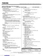
1.5.3  Rear Components

The rear components are shown in the following figure and identified in this section:

1  

Serial connector

2  

Serial number

3  

Parallel connector

4  

External monitor connector

5  

Docking connector

6  

Airflow vents

7  

USB connector

8  

Keyboard/Mouse connector

Figure 1-4. 

Rear Components

Summary of Contents for Armada 1500C series

Page 1: ...Thank you for purchasing this Factory Service Manual CD DVD from servicemanuals4u com Please check out our eBay auctions for more great deals on Factory Service Manuals servicemanuals4u ...

Page 2: ...n or specific instructions NOTE Text set off in this manner presents commentary sidelights or interesting points of information Technician Notes WARNING Only authorized technicians trained by Compaq should attempt to repair this equipment All troubleshooting and repair procedures are detailed to allow only subassembly module level repair Because of the complexity of the individual boards and subas...

Page 3: ...lowing documentation is available to support the computer Compaq Armada 1500c Series documentation set Microsoft operating system user s guide Service Training Guides Compaq Service Advisories and Bulletins Compaq QuickFind Compaq Service Quick Reference Guide Compaq Armada 1500c Series Maintenance and Service Guide Compaq Armada 1500c Series Illustrated Parts Map Compaq Internet site at http www ...

Page 4: ... 1500c Series is a line of multimedia notebook computers with advanced modularity processors and video graphics This full function Celeron based series of notebook computers allows full desktop functionality and connectivity through the use of an optional Convenience Base II Figure 1 1 Compaq Armada 1500c Personal Computer ...

Page 5: ...ted T cursor control keys and embedded numeric keypad Four user programmable keys Touchpad pointing device Power Sources include the following Internal Nickel Metal Hydride NiMH modular battery pack External AC adapter Power management and security features Two standard device slots that will accommodate two type I or II PC Cards or one type III PC Card PCMCIA and CardBus cards 176 pin expansion c...

Page 6: ...ence Base II with Ethernet 1 3 2 System Memory Options The computer supports optional 16 32 64 and 128 MB memory boards The memory boards are 66 MHz SDRAM without parity System memory can be expanded to 160 MB of DRAM Table 1 1 describes the possible memory configurations for the computer Table 1 1 Memory Configuration SODIMM Module Present Total System Memory No SODIMM present 32 MB 16 MB 48 MB 3...

Page 7: ...nuously adjustable tilt angle 1 4 2 Internal Boards The system electronics are integrated on seven printed circuit assemblies the LED status board I O fixture connector audio board system board modem board and the DC DC converter board An optional memory board is available that expands the system memory up to 160 MB The LED status board connects the system board to the display cables and supports ...

Page 8: ...unit The local bus video adapter is the Chips and Technologies 69000 controller The serial parallel port board expands the serial and parallel signals from the system board to the serial and parallel expansion connectors The audio board supports the microphone and headphone jacks the volume control switches and the amplifier and equalization circuitry 1 4 3 Video System The standard video subsyste...

Page 9: ...ont and Left Side Components The front and left side external components are shown in the following figure and identified in this section 1 Display latches 2 Power connector 3 RJ 11 connector on some models 4 PC Card eject levers 5 PC Card slots 6 DualBay compartment 7 Power Suspend light 8 Battery charge light Figure 1 2 Front and Left Side Components ...

Page 10: ...ht side external components are shown in the following figure and identified in this section 1 Battery bay 2 Stereo speaker headphone jack 3 Microphone jack 4 Volume control buttons 5 CD ROM drive or DVD ROM drive 6 Cable lock provision Figure 1 3 Right Side Components ...

Page 11: ...components are shown in the following figure and identified in this section 1 Serial connector 2 Serial number 3 Parallel connector 4 External monitor connector 5 Docking connector 6 Airflow vents 7 USB connector 8 Keyboard Mouse connector Figure 1 4 Rear Components ...

Page 12: ...nts are shown in the following figure and are identified in this section 1 Docking latch receptacles 2 Docking alignment guide 3 Modem compartment 4 Diskette drive 5 Diskette drive release latch 6 Battery with traction grip 7 Docking restraint latch recess Figure 1 5 Bottom Components ...

Page 13: ...5 Status Panel Lights The status panel lights are shown in the following figure and are identified in this section 1 Hard drive light 2 Diskette drive light 3 NumLk light 4 Caps Lock light 5 Scroll Lock light Figure 1 6 Status Panel Lights ...

Page 14: ...nd the error message does not return When the problem is resolved stop performing the troubleshooting steps and do not complete the remaining recommended actions Refer to Chapter 5 Computer Removal and Replacement Procedures for removal and replacement procedures that are recommended If the problem is intermittent check the computer several times to verify that the problem is solved The following ...

Page 15: ...he password and press Enter 7 Use the Hotkey Fn F10 to adjust brightness to midrange and leave the display open 8 Turn off the computer and all external devices 9 Disconnect external devices that you do not want to test If you want to use the printer to log error messages leave it connected to the computer NOTE If a problem only occurs when an external device is connected to the computer the probl...

Page 16: ...he computer During Power On Self Test POST a 162 System Options not set message appears 7 Shut down the computer then disconnect the external power supply again 8 Replace the real time clock battery 9 Install the battery pack s 10 Proceed with the troubleshooting procedures 2 3 Power On Self Test POST The Power On Self Test POST is a series of tests that run every time the computer is turned on PO...

Page 17: ...p Computer Setup replaces the SCU utility If you receive one of the error messages listed below follow the recommended action Table 2 1 Warning Messages Message Description Recommended Action CMOS checksum invalid run SCU CMOS RAM information has been corrupted and needs to be reinitialized Run Computer Setup to reinitialize CMOS RAM CMOS failure run SCU CMOS RAM has lost power Run Computer Setup ...

Page 18: ... is not occurring Replace the system board RAM parity error at location xxxx A RAM parity error occurred at the specified hex location Press F1 ROM at xxxx LENGTH yyyy with nonzero checksum zz An illegal adapter ROM was located at the specified address Check the external adapter such as a video card to determine if it is causing the conflict Time Date corrupt run SCU The time and date stored in th...

Page 19: ...it 4 Refresh Detect failed to toggle within an allotted amount of time 1 Interrupt controller failed A sequential read write of various Interrupt Controller registers failed 5 ROM checksum incorrect A checksum of the ROM BIOS does not match the byte value at F000 FFFF 2 RAM error at location xxxx RAM error occurred during memory test None Table 2 3 Fatal Error Beep Codes Beep Code Beep Sequence De...

Page 20: ...o allow you to set custom features such as security options power conservation levels and startup preferences If you are running Windows 95 or later the computer automatically recognizes and configures the system for new devices If you have a configuration problem or want to view or reset configuration settings you can use Computer Setup NOTE If you are running Windows 95 or later you should use C...

Page 21: ...and serial ports ISA ISA bus and connected devices PCI PCI bus and connected devices PC Card PC Card devices Running Computer Setup 1 Turn on or restart the computer by clicking Start Shut Down Restart the computer 2 Press F10 when the blinking cursor appears in the upper right corner of the screen NOTE If your a setup password is enabled it must be used to access Computer Setup 3 Click a language...

Page 22: ... can interrupt the program 2 Connect a printer if you want to print a log of error messages 3 Turn on the external devices that you want to test 4 Turn on or restart the computer 5 Access Compaq Utilities by pressing F10 when the blinking cursor appears in the upper right corner of the display 6 Click Computer Checkup View the Device List If the list of installed devices is correct click OK If the...

Page 23: ... Processor Test Error Codes Error Code Description Recommended Action 101 xx CPU test failed Replace the processor board and retest 103 xx DMA page registers test failed Replace the system board and retest 104 xx Interrupt controller master test failed 105 xx Port 61 error 106 xx Keyboard controller self test failed 107 xx CMOS RAM test failed 108 xx CMOS interrupt test failed 109 xx CMOS clock te...

Page 24: ...ies to test port 4 Check port and IRQ configuration 5 Replace the system board and retest NOTE Fn F11 clears the ESCD configuration information If the Fn F11 sequence is pressed very early after powering the machine on after you see the keyboard LEDs blink but before the video is initialized CMOS memory will be invalidated The ESCD is cleared the machine is reset and boots with the 162 System Opti...

Page 25: ...al port test failed 1 Check port configuration 2 Replace the system board and retest Table 2 10 Hard Drive Test Error Codes Error Code Description Recommended Action 1701 xx Hard drive format test failed 1 Run Compaq Utilities and verify drive type 1702 xx Hard drive read test failed 2 Verify that all secondary drives have secondary drive capability 1703 xx Hard drive write read compare test faile...

Page 26: ...lowing actions apply to error codes 2402 xx through 2456 xx 2403 xx Video attribute test failed 1 Run Compaq Utilities 2404 xx Video character set test failed 2 Disconnect external monitor and test with internal LCD display 2405 xx Video 80 25 mode 9 14 character cell test failed 3 Replace the display assembly and retest 4 Replace the system board and retest 2406 xx Video 80 25 mode 8 8 character ...

Page 27: ...m configuration 2 Verify that the audio led board is properly seated 3 Verify display audio cable connection 3206 xx Audio System Internal Error Replace the audio board and retest Table 2 13 Pointing Device Interface Test Error Codes Error Code Description Recommended Action 8601 xx Pointing device test failed Replace the keyboard CPU cover assembly 8602 xx Interface test failed Table 2 14 CD ROM ...

Page 28: ...Utilities by pressing F10 when the cursor blinks in the upper right corner of the display 4 If prompted select a language 5 Click View System Information INSPECT 6 Click the item you want to view The list includes System Audio ROM Operating system Keyboard System files System ports Windows files System storage Miscellaneous Graphics Memory Network applicable only if computer is docked in the Conve...

Page 29: ... Click the System Features icon Boot Management box MultiBoot tab 3 Designate the hard drive boot startup sequence you want 4 Click OK to accept the changes 2 5 6 Factory Default Settings Table 2 15 Factory Default Settings Initialization Enable POST Memory Test Checked enabled Keyboard NumLk Unchecked Off 1 Hard drive in the computer 2 Hard drive in the computer MultiBay Boot display Auto Languag...

Page 30: ...uspend Time 10 minutes Hibernation Timeout 1 hour Drive Timeout 6 minutes Screen Timeout 4 minutes Custom Suspend Time disabled Hibernation Timeout low battery Drive Timeout always on Screen Timeout always on Security Enable QuickLock QuickBlank Unchecked Disabled Enable Power On Password Unchecked Disabled Disable Serial Infrared Ports Unchecked Enabled Disable Parallel Port Unchecked Enabled Dis...

Page 31: ...d Verify that all printer drivers have been installed 2 6 2 Checklist for Solving Problems If you encounter a minor problem with the computer or software applications go through the following checklist for possible solutions Is the computer connected to an external power source or does it have a fully charged battery pack installed Are all cables connected properly and securely Did the diskette dr...

Page 32: ...l and or the software volume control needs to be adjusted In Windows 95 or later adjust the computer volume control buttons and adjust the volume control in Multimedia Properties NOTE The volume control in Multimedia Properties only affects the Wave audio sources such as system sounds and wav file playback To change other sources such as MIDI video sound and game effects use the Volume Control app...

Page 33: ...icrophone may not be connected properly Ensure that the microphone plug is properly connected to the mono microphone jack Sound source is not selected Ensure that microphone is selected as the recording source in Control Panel Multimedia and that the recording level is adjusted No sound from game program Audio settings are not set correctly Check the game program audio settings Computer volume con...

Page 34: ...by pressing Fn F8 Computer beeped five times and battery light is blinking Computer has entered a low battery condition Immediately save any open file s Then do one of the following 1 Connect the computer to an external power source 2 Turn the computer off and replace the battery pack Computer battery light blinks to indicate low battery condition but computer does not beep Low battery beeps were ...

Page 35: ...computer is disconnected from the external power for more than two weeks remove the battery pack to reduce the self discharge rate Power management is disabled Press Fn F7 and set the power conservation level An external device or PC Card is draining the battery Turn off or disconnect external devices when not using them Computer is beeping and battery power light is blinking Battery pack charge i...

Page 36: ...are using Windows NT format the diskette by entering format a at the system prompt Diskette drive cannot write to a diskette Diskette is not formatted Format the diskette If you are using Windows 95 or later 1 From the Windows 95 or later desktop double click My Computer 2 Click 3 Floppy A File Format 3 Fill in the required information then click Start If you are using Windows NT format the disket...

Page 37: ...d drive has bad sectors or has failed Do one of the following If you are running Windows 95 or later access ScanDisk by clicking Start Programs Accessories System Tools ScanDisk then check the Automatically fix errors box Click Start to begin scanning If you are running Windows NT go to the system prompt and type chkdsk to scan for errors Reformat the hard drive Contact your Compaq authorized deal...

Page 38: ... came with the new device for installation instructions Cable s of new external device are loose or power cables are unplugged Ensure that all cables are properly and securely connected and the power cord is plugged into an electrical outlet Power switch of new external device is not turned on 1 Turn off the computer 2 Turn on the external device 3 Turn on the computer to integrate the device with...

Page 39: ...abeled This location has call waiting Select 70 70 or 1170 from the drop down list to disable call waiting for your dialing area Noisy telephone line Phone line noise causing garbled or missing characters or slow data transfer speeds Check your telephone and modem cable connections If they are a little loose they can cause noise on the line Check with your local telephone company for a phone line ...

Page 40: ...he Enter key 3 If the modem displays OK the modem and computer are working together If the modem displays ERROR or does not respond restart the computer and repeat step 1 4 Type ATDT and listen for a dial tone 5 Type ATH0 zero to hang up Speaker Control AT Command ATM is set to 0 Set the Speaker Control to 1 1 Click Start Programs Accessories HyperTerminal 2 Go to Command Mode type ATM1 and press ...

Page 41: ...ices can work on the same phone line To use another telephony device on the same line in these countries unplug the modem cable from the wall jack first Modem does not dial correctly under Windows 95 or later Switzerland and Germany only The Wait for dial tone before dialing check box is checked This causes Windows 95 or later to issue an ATDT command A typical dial string would look like this ATD...

Page 42: ...nager PCMCIA Socket Double click the Texas Instruments TI 1131 CardBus controller to view device properties Deselect the Disable in this hardware profile check box Card or card driver is not compatible with the computer or with the operating system Contact service provider for a list of compatible PC Cards Computer beeps twice but modem and or fax does not work Telephone cord is not plugged in all...

Page 43: ...ormation at the point where Hibernation was initiated NOTE To change the Hibernation timeout setting in Windows 95 or later click the Hibernation tab in Power Properties In Windows NT run Computer Setup and select Power Management Computer turned off while it was left unattended and will not turn on System initiated Hibernation and or shut down because of a critical low battery condition Replace t...

Page 44: ...reen save was initiated after the Power Management timeout period Press any key or click the mouse Brightness or contrast needs adjusting Adjust the control s with the hotkeys Fn F9 and Fn F10 Screen has overheated If computer is in direct sunlight move it and allow it to cool Computer screen is blank and the screen on an external monitor displays information Display was switched to the external m...

Page 45: ...ice to restore the display 2 If display remains distorted turn off the monitor then turn it on again 3 Disable the monitor energy saving feature in Display Properties or in Computer Setup Power Management The image has a black border and does not fill the screen The Desktop Area setting is smaller than the Resolution setting Adjust the settings for the Desktop Area and Resolution Double click Cont...

Page 46: ...d Reduce the number of connected external USB devices to no more than two hubs on the first tier and no more than one keyboard and one pointing device on the first or second tier External devices in lower tiers do not work An unpowered hub is connected to another unpowered hub Use only powered hubs Make sure that all unpowered hubs are immediately preceded by powered hubs in the USB chain Solving ...

Page 47: ...ay resident TSR applications are running Remove from memory any TSR applications you do not need Solving Keyboard and Mouse Problems Table 2 29 Solving Keyboard Problems Problem Probable Cause Recommended Action s External keyboard does not work External keyboard may not be securely connected ro may be connected to an incorrect external connector Ensure that the external keyboard is properly and s...

Page 48: ...oblems Problem Probable Cause Recommended Action s A new device is not recognized as part of the computer system Power switch of the new external device was not turned on before the system was turned on Initiate Suspend ensure the external device is connected properly and turn on the external device then exit Suspend ...

Page 49: ...2 36 Troubleshooting ...

Page 50: ...LLUSTRATED PARTS CATALOG This chapter provides illustrated parts and references for spare parts for the Armada 1500c Series To review an illustrated parts breakdown of the computer refer to the Illustrated Parts Map that comes with this guide ...

Page 51: ...3 2 Illustrated Parts Catalog 3 1 System Unit Figure 3 1 System Unit ...

Page 52: ...French 254968 051 Keyboard French Canadian 254968 121 Keyboard German 254968 041 Keyboard Italian 254968 061 Keyboard Japanese 254968 191 Keyboard Korean 254968 033 Keyboard Latin American Spanish 254968 161 Keyboard Norwegian 254968 101 Keyboard Portuguese 254968 131 Keyboard Spanish 254968 071 Keyboard Swedish Finnish 254968 091 Keyboard Swiss 254968 111 Keyboard Taiwanese 254968 034 Keyboard UK...

Page 53: ...alBay Devices Item Description Spares Part Number 1 24x CD ROM drive 401102 001 DVD ROM drive 401097 001 2 4 0 GB hard drive 310344 001 5 0 GB hard drive 310364 001 6 0 GB hard drive 310365 001 10 0 GB hard drive 102139 001 3 1 44 MB diskette drive 254962 001 4 Lithium Ion battery pack 107163 001 Nickel Metal Hydride battery pack 107150 001 Not illustrated ...

Page 54: ... AC Power cord US Canada 246959 001 6 AC Power cord Australia New Zealand 246959 011 6 AC Power cord Denmark 246959 081 6 AC Power cord Europe 246959 021 6 AC Power cord Italy 246959 061 6 AC Power cord Japan 246959 291 6 AC Power cord Korea 246959 AD1 6 AC Power cord Swiss 246959 111 6 AC Power cord UK 246959 031 4 RTC Battery 254971 001 5 Microphone part of plastics kit 254981 001 6 External AC ...

Page 55: ...B 66 MHz SDRAM 313911 001 Memory board SODIMM 64 MB 66 MHz SDRAM 313918 001 Memory board SODIMM 128 MB 66 MHz SDRAM 310345 001 2 LED status board 12 1 inch CSTN display 401098 001 LED status board 12 1 inch CTFT display 401103 001 3 I O connector 254956 001 4 DC DC converter 401106 001 5 Audio board 401096 001 6 System board 266 MHz CPU with 128K cache 401104 001 System board 300 MHz CPU with 128K...

Page 56: ...ptions Table 3 5 Options Item Description Spares Part Number 1 External AC adapter with DC power cord US Canada 401095 001 2 Automobile Aircraft adapter 313919 001 3 Lithium Ion battery pack 254960 001 4 External battery charger 254970 001 Not illustrated ...

Page 57: ...ics kit includes Left clutch cover 254981 001 2 Microphone Display cable cover 3 Right clutch cover 4 RTC battery cover 5 CD ROM DVD ROM access door 6 Modem access door Rubber feet for base enclosure assembly 7 Fan 108857 001 Logo kit 401099 001 Miscellaneous parts kit includes microphone 254981 001 Screw kit 254980 001 Return Kit 254972 001 Not illustrated ...

Page 58: ...Table 3 7 Documentation Item Description Spares Part Number Armada 1500c Series Illustrated Parts Map 10 ea 104694 001 Armada 1500c Series Maintenance and Service Guide 104695 001 Armada 1500c Series Reference Guide 104726 001 Country kit 103591 001 ...

Page 59: ...3 10 Illustrated Parts Catalog ...

Page 60: ...r or other conductor can destroy static sensitive devices or microcircuitry Often the spark is neither felt or heard but damage occurs An electronic device exposed to electrostatic discharge ESD may not be affected at all and will work perfectly throughout a normal cycle Or it may function normally for a while then degrade in the internal layers reducing its life expectancy Networks built into man...

Page 61: ...e the degree of sensitivity The following proper packaging and grounding precautions are necessary to prevent damage Protect all electrostatic parts and assemblies with conductive or approved containers or packaging Keep electrostatic sensitive parts in their containers until they arrive at static free stations Place items on a grounded surface before removing them from their container Always be p...

Page 62: ...vent static damage at the workstation Cover the workstation with approved static dissipative material Provide a wrist strap connected to the work surface and properly grounded tools and equipment Use static dissipative mats heel straps or air ionizers to give added protection Handle electrostatic sensitive components parts and assemblies by the case or PCB laminate Handle them only at static free ...

Page 63: ...ce between operator and ground To be effective the conductive strips must be worn in contact with the skin Recommended Materials and Equipment Other materials and equipment that are recommended for use in preventing static electricity include Anti static tape Anti static smocks aprons and sleeve protectors Conductive bins and other assembly or soldering aids Conductive foam Conductive table top wo...

Page 64: ...or unseat the cables during insertion or removal from connectors Handle cables by the connector or pull tabs whenever possible In all cases avoid bending twisting or tearing the cables and ensure that cables are placed in such a way that they cannot be caught or snagged by parts being removed or replaced CAUTION Improper cable placement can cause severe damage to the unit Ensure that cables are pl...

Page 65: ...4 6 Removal and Replacement Preliminaries ...

Page 66: ...for the computer 5 1 Serial Number The computer serial number should be provided to Compaq support when requesting information or ordering spare parts The serial number is displayed on the rear of the CPU Figure 5 1 Figure 5 1 Serial Number NOTE This model does not have an AC connector port It has a recessed sealed opening to allow docking with a convenience base ...

Page 67: ...0 Microphone Display Cable Cover and Microphone 5 11 Clutch Covers Display Assembly 5 11 1 Clutch Covers 5 11 2 Display Assembly 5 12 Top Cover Assembly 5 13 LED Status Panel 5 14 Audio Board and Audio Cable 5 15 DC DC Converter 5 16 Fan 5 17 I O Fixture Connector 5 18 System Board 5 19 External Computer Components 5 19 1 Computer Logo 5 19 2 Computer Feet 5 3 Preparing the Computer for Disassembl...

Page 68: ...l power supply from the computer If the computer is docked in the convenience base see Section 5 3 2 for undocking instructions 5 3 2 Undocking the Computer If the computer is docked in the convenience base it must be undocked before performing additional work Complete the following steps to undock the computer If the computer is not docked in the convenience base proceed to Section 5 3 3 1 Discon...

Page 69: ...to the battery compartment Do not force the battery pack into the handle if insertion does not occur easily WARNING Do not crush puncture or incinerate the battery pack Do not dispose of in water Do not expose to temperatures higher than 60 C Do not open a battery pack because this damages the pack makes it unserviceable and exposes potentially harmful battery components There are no field service...

Page 70: ...install the battery pack 1 Insert the battery into the battery compartment 2 Push firmly until the battery pack is seated into place 1 Figure 5 3 Inserting the Battery Pack CAUTION Installing the battery pack upside down can cause the contacts to break ...

Page 71: ... Do not expose to temperatures higher than 60 C Do not open a battery pack because this damages the pack makes it unserviceable and exposes potentially harmful battery components There are no field serviceable parts located inside the battery pack NOTE If a battery pack is used in the DualBay use the battery release latch to release the battery Either a diskette drive or a modular battery pack may...

Page 72: ...and Replacement Procedures 5 7 To install the DualBay device 1 Insert the diskette drive into the DualBay compartment 2 Push firmly until the diskette drive is seated into place Figure 5 5 Installing the DualBay Device ...

Page 73: ...ard eject lever to the forward position 1 2 Press the PC card eject button 2 3 Pull the PC card out of the PC Card slot 3 Figure 5 6 Removing the PC Card To install a PC card insert the card into the slot and press firmly until it is seated NOTE Before replacing the system board the PC card eject levers must be in the forward position See Section 5 18 on removing the system board ...

Page 74: ...h a modem the modem compartment is sealed off by a protective plate For models equipped with a modem complete the following steps for removal 1 Turn the computer bottom side up 2 Remove two screws from the base enclosure and remove the modem access door 1 3 Carefully pull the modem board release tab 2 Figure 5 7 Removing the Modem Access Door ...

Page 75: ...5 10 Computer Removal and Replacement Procedures 4 Carefully lift the modem board and remove Figure 5 8 Removing the Modem To replace or install the modem reverse the procedure ...

Page 76: ... a DVD ROM drive may be installed in the unit For convenience a CD ROM drive is depicted in this sequence To remove the CD ROM or DVD ROM drive and access door 1 Turn the computer bottom side up 2 Remove two screws from the CD ROM access door Figure 5 9 Removing the CD ROM or DVD ROM Drive Access Door ...

Page 77: ...5 12 Computer Removal and Replacement Procedures 3 Remove the CD ROM Figure 5 10 Removing the CD ROM or DVD ROM Drive To install the CD ROM drive reverse the procedure ...

Page 78: ...tion 5 3 5 5 Turn the computer bottom side up 6 Remove the screws near the rear of the computer from the battery and DualBay compartments and from the bottom of the base 1 These screws remove the keyboard NOTE It is not necessary to remove the screws 2 unless you are going to remove the top cover assembly 7 Remove the upper screws 2 from the battery and DualBay compartments These are the remaining...

Page 79: ...Lift the keyboard and rest it on the keyboard slots on the top cover NOTE It is not necessary to disconnect the keyboard cable to remove the memory expansion board hard drive or RTC battery 10 Slide back the ZIF connector to release the keyboard cable Figure 5 12 Lifting the Keyboard ...

Page 80: ...ocedures 5 15 11 Slide the keyboard cable strain relief tab toward you then pull the tab up to remove it from the slot 12 Carefully lift the keyboard up and away Figure 5 13 Removing the Keyboard To replace the keyboard reverse the steps ...

Page 81: ...ack Section 5 3 3 3 Remove the DualBay device Section 5 3 4 4 Remove any PCMCIA cards Section 5 3 5 5 Raise the keyboard Section 5 6 CAUTION Release the locking tabs that secure the memory expansion board in the slot Failure to release the locking tabs can break the connectors and damage the system board 6 Release the right 1 and left 2 locking tab at each end of the memory expansion board This re...

Page 82: ...Computer Removal and Replacement Procedures 5 17 7 Lift 1 the free edge of the memory expansion board slightly and pull 2 it straight out of the slot Figure 5 15 Removing the Memory Expansion Board ...

Page 83: ...ert the memory expansion board into the memory slot 1 2 Pivot the memory expansion board so that it lays flat in the memory compartment 2 3 Push the memory expansion board firmly into place to seat the connections and to engage the locking tabs Figure 5 16 Installing the Memory Expansion Board ...

Page 84: ...xternal devices Section 5 3 1 2 Remove the battery pack Section 5 3 3 3 Remove the DualBay device Section 5 3 4 4 Remove any PCMCIA cards Section 5 3 5 5 Raise the keyboard Section 5 6 6 Remove hard drive retaining clip by squeezing both ends of the retaining clip 1 together then lifting up 2 Figure 5 17 Removing the Hard Drive Retaining Clip ...

Page 85: ... Removal and Replacement Procedures 7 Slide the hard drive to the right 8 Lift the hard drive from the hard drive compartment Figure 5 18 Removing the Hard Drive Reverse the above procedure to install the hard drive ...

Page 86: ...re part for this computer CAUTION Rock the RTC battery cable connector from side to side to disconnect it Failure to do so can damage the RTC battery cable To remove the Lithium real time clock RTC battery 1 Disconnect the AC power and any external devices Section 5 3 1 2 Remove the battery pack Section 5 3 3 3 Remove the DualBay device Section 5 3 4 4 Remove any PCMCIA cards Section 5 3 5 5 Raise...

Page 87: ...moval and Replacement Procedures 7 Disconnect the RTC battery connector from the system board 1 8 Remove the RTC battery 2 Figure 5 20 Removing the RTC Battery Reverse the procedure to install a replacement RTC battery ...

Page 88: ... remove the microphone and microphone display cable cover 1 Disconnect the AC power and any external devices Section 5 3 1 2 From the rear of the computer remove two screws securing the microphone display cable cover from the base enclosure Figure 5 21 Removing the Microphone Display Cable Cover Screws ...

Page 89: ...icrophone display cable cover by rotating the cover 1 and lifting it from the rear of the computer 2 Figure 5 22 Removing the Microphone Display Cable Cover 4 Disconnect the microphone from the audio cable 5 Remove the microphone Figure 5 23 Removing the Microphone ...

Page 90: ...dures 5 25 5 11 Clutch Covers Display Assembly 5 11 1 Clutch Covers To remove the left and right clutch covers lift them from the ends of the computer Figure 5 24 Removing the Clutch Covers Reverse the procedure to install the clutch covers ...

Page 91: ...ews from each clutch and the clutch tension plate that secure the display to the base enclosure 1 8 Disconnect the display cables from the base enclosure 2 9 Lift the display assembly from the base enclosure Figure 5 25 Removing the Display Assembly Reverse the procedure to replace the display assembly CAUTION Attach the ground cable before attaching the display cables when replacing the display a...

Page 92: ...ion 5 3 3 3 Remove the DualBay device Section 5 3 4 4 Remove any PCMCIA cards Section 5 3 5 5 Remove the keyboard Section 5 6 6 Remove the microphone display cable cover Section 5 10 7 Disconnect speaker connectors 1 and touchpad cable 2 and RTC battery connector 3 from the system board Figure 5 26 Disconnecting the Speaker Connectors Touchpad Connector and RTC Battery Connector From the System Bo...

Page 93: ...5 28 Computer Removal and Replacement Procedures 8 From the rear of the computer remove four screws securing the top cover assembly to the base enclosure Figure 5 27 Removing Top Cover Assembly Screws ...

Page 94: ...uter Removal and Replacement Procedures 5 29 9 Carefully remove the top cover assembly from the base enclosure Figure 5 28 Removing the Top Cover Assembly To replace the top cover assembly reverse the steps ...

Page 95: ...ve any PCMCIA cards Section 5 3 5 5 Remove the keyboard Section 5 6 6 Remove the microphone display cable cover and microphone Section 5 10 7 Remove the clutch covers display assembly Section 5 11 1 8 Remove the top cover assembly Section 5 12 9 Remove the 2 screws 1 securing the status panel board 10 Disconnect the LED status panel board 2 from the system board Figure 5 29 Removing the LED Status...

Page 96: ...eyboard Section 5 6 7 Remove the microphone display cable cover and microphone Section 5 10 8 Remove the clutch covers display assembly Section 5 11 1 9 Remove the screw 1 from the audio board 10 Disconnect the audio cable 2 11 Slide the audio board 3 from the connector on the system board and remove the audio board Figure 5 30 Removing the Audio Board CAUTION Do not use the long T 8 screw to secu...

Page 97: ...emove the DualBay device Section 5 3 4 4 Remove any PCMCIA cards Section 5 3 5 5 Remove the keyboard Section 5 6 6 Remove the microphone display cable cover and microphone Section 5 10 7 Remove the clutch covers display assembly Section 5 11 1 8 Remove the top cover assembly Section 5 12 9 Remove the screw that secures the DC DC converter to the base enclosure Figure 5 31 Removing the DC DC Conver...

Page 98: ...he DC DC converter from the I O fixture connector 1 12 Remove the DC DC converter 2 Figure 5 32 Disconnecting and Removing the DC DC Converter To replace the DC DC converter reverse the steps CAUTION The DC DC converter board is secured by a short T 8 screw Do not use the long T 8 screw to secure the DC DC converter board Use of the long screw can damage the system board ...

Page 99: ...eyboard Section 5 6 6 Remove the microphone display cable cover and microphone Section 5 10 7 Remove the clutch covers display assembly Section 5 11 1 8 Remove the top cover assembly Section 5 12 9 Disconnect the fan from the system board 10 Remove the fan from the base enclosure Figure 5 33 Removing the Fan Reverse the procedure to install the fan IMPORTANT When installing the fan orient the fan ...

Page 100: ...vice Section 5 3 4 4 Remove any PCMCIA cards Section 5 3 5 5 Remove the keyboard Section 5 6 6 Remove the microphone display cable cover Section 5 10 7 Remove the clutch covers display assembly Section 5 11 1 8 Remove the top cover assembly Section 5 12 9 Remove the LED status panel board Section 5 13 10 Remove three screws securing the I O fixture to the rear of the computer Figure 5 34 Removing ...

Page 101: ...5 36 Computer Removal and Replacement Procedures 11 Remove the I O fixture connector Figure 5 35 Removing the I O Fixture Connector To replace the I O fixture connector reverse the steps ...

Page 102: ...ay device Section 5 3 4 4 Remove any PCMCIA cards Section 5 3 5 5 Remove the top cover assembly Section 5 12 6 Remove the I O fixture connector Section 5 17 7 Remove the screws 1 securing the system board to base enclosure 8 Disconnect the CD ROM DVD ROM cable 2 9 Remove the two screws 3 from the rear of the computer that secure the expansion connector to the base enclosure Figure 5 36 Disconnecti...

Page 103: ...system board away from the base enclosure 2 Figure 5 37 Removing the System Board To replace the system board reverse the steps NOTE Before replacing the system board the PC card eject levers must be in the forward position See Section 5 3 5 for proper positioning of the PC card eject levers ...

Page 104: ...nd can be replaced if damaged To replace the logo 1 Use a small sharp flat bladed screwdriver to pry up the existing logo 2 Clean the area with a clean dry cloth 3 Apply the new logo 5 19 2 Computer Feet There are four locations where the computer feet can be applied To replace the computer feet 1 Peel the old foot from the computer Use a razor blade if needed to lift a corner of the foot free fro...

Page 105: ...5 40 Computer Removal and Replacement Procedures ...

Page 106: ...des physical and performance specifications for the following Computer Displays Hard drive Diskette drive CD ROM drive DVD ROM drive Battery packs External power supplies The chapter also includes System interrupts System DMA System I O addresses System memory map ...

Page 107: ...imum transient 4 50 kV Maximum input power 75W Automobile Aircraft Adapter DC Input Requirements Operating voltage 11 to 16 VDC Operating power 85 0 W Temperature Operating 50 to 95 F 10 to 35 C Non operating 22 to 140 F 30 to 60 C Relative Humidity noncondensing Operating 10 to 90 Non operating tw 38 7 C max 5 to 90 Altitude Operating 0 to 10 000 ft 0 to 3 480 m Non operating 0 to 30 000 ft 0 to ...

Page 108: ...tripe Brightness Minimum No flickering 100cd m nits typical 90cd m nits minimum Backlight Edge Lit Character Display 80 25 Table 6 3 12 1 Inch CTFT SVGA Display U S Metric Dimensions maximum Height 7 67 in 195 0 mm Width 10 80 in 275 0 mm Number of Colors 262 K Contrast Ratio 100 1 minimum Pixel Resolution Pitch Format Configuration 03075 x 0 3075 mm 800 x 600 RGB Stripe Brightness 130 cd m nits t...

Page 109: ... 75 Transfer Rate Media Mb s 51 4 83 4 MB s Interface Mb s 16 6 MB sec Sector Interleave 1 1 Typical Seek Time Including setting Single Track ms 4 ms Average ms 13 ms read Full Stroke ms 32 ms read Disk Rotational Speed RPM 4009 Physical Configuration Cylinders 6975 Data Heads 6 Sectors Track 144 to 240 Bytes Sector 512 Logical Configuration Cylinders 7944 Heads 16 Sectors per Track 63 Bytes per S...

Page 110: ...density 720 KB Light None Height 0 43 in 11 mm Bytes per sector 512 Sectors per Track High density 18 1 44 MB 15 1 2 MB Low density 9 Tracks per Side High density 80 1 44 MB 80 1 2 MB Low density 80 Read Write heads 2 Average Seek Times Track to Track high low 3 ms 6 ms Average high low 94 ms 174 ms Settling Time 15 ms Latency Average 100 ms ...

Page 111: ...5 mm Disc Diameter 12 cm 8 cm Disc Thickness 1 2 mm Track Pitch 1 6 µm Laser Beam divergence 53 5 1 5 degrees Output power 0 24 0 1 mw Type Semiconductor Laser GaA1As Wave length 780 nm 25 nm Access time Random 350 ms Full stroke 750 ms Audio output level Line out 0 7 Vrms Headphone None Cache Buffer 128 KB Data transfer rate Sustained 24x 3 6 MB s Sustained single 150 KB sec Burst 8 3 MB sec Star...

Page 112: ...h 1 6 µm Capacity 4 7 GB DVD 5 8 5 GB DVD 9 9 4 GB DVD 10 550 Mbytes Mode 1 12 640 Mbytes Mode 2 12 cm 180 Mbytes 8 cm 17 1 DVD 18 Laser Output power 5mw Type Semiconductor laser GaA1As Wave length 650 nm 25 nm DVD Mode 795 nm 25 nm CD ROM mode Access time Random 200 ms Full stroke 250 ms Audio output level Line out 0 7 Vrms Headphone None Cache Buffer 128 KB Data Transfer Rate Sustained 1x CD ROM...

Page 113: ...l Requirements Operating temperatures 50 F to 95 F 10 C to 35 C Non operating temperatures 22 F to 140 F 30 C to 60 C Table 6 9 Lithium Ion Battery Pack U S Metric Dimensions Height 0 82 in 20 8 mm Length 5 8 in 147 32 mm Width 3 2 in 81 3 mm Electrical Voltage 14 4 VDC Watt hour capacity 39 Wh Battery Life up to 2 5 hours Environmental Requirements Operating temperatures 50 F to 95 F 10 C to 35 C...

Page 114: ...r U S Metric Dimensions Height 1 42 in 36 mm Width 2 83 in 72 mm Length 4 84 in 123 mm Weight 0 88 lb 400 gm Input Cord Length 3 281 ft 1 0 m Power Supply Input Nominal voltage 13 8 VDC Operating voltage 10 5 14 8 VDC Maximum voltage 16 0 VDC Input fuse protection 8 0 A Temperature Operating 32 to 104 F 0 to 40 C Non operating 4 to 140 F 20 to 60 C Relative Humidity Operating 10 to 90 Non operatin...

Page 115: ...ating 22º to 140ºF 30º to 60ºC Relative Humidity Operating 10 to 90 Non operating 10 to 95 Table 6 12 External Battery Charger U S Metric Dimensions Height 1 57 in 40 mm Width 5 25 in 133 mm Length 9 4 in 239 mm Weight 1 1 lb 4 95 gm Power Supply Input Nominal voltage 18 5 0 25 VDC Current 40 to 42 W Power Supply Output Nominal voltage 18 5 0 25 VDC Current 40 to 42 W Temperature Operating 41 to 1...

Page 116: ...oller IRQ7 Used by either EPP parallel or audio IRQ8 Real time clock MSIO IRQ9 Used by either audio or PCMCIA controller IRQ10 Used by either audio or PCMCIA controller IRQ11 Used by PCMCIA IRQ12 Mouse IRQ13 Floating point error input IRQ14 Hard drive IRQ15 Convenience base NIC interrupt 6 10 System DMA Table 6 14 System DMA Hardware DMA System Function DMA 0 Not assigned DMA 1 Audio controller DM...

Page 117: ...ort B 062 063 Unused 064 Keyboard command status 065 06F Unused 070 CMOS index address 071 CMOS data 072 073 Unused 074 Reserved 075 Unused 076 Reserved 077 077F Unused 080 08F DMA page registers 084 085 POST code output port 090 091 Unused 092 Fast reset register 093 09F Unused 0A0 0A1 Interrupt controller 2 0A2 0BF Unused 0C0 0DF DMA controller 2 0E0 0E1 ESS audio configuration 0E2 0E5 Configura...

Page 118: ...d 370 371 Reserved 372 Diskette digital output register 373 Unused 374 Reserved 375 Diskette main status data registers 376 Reserved 377 Diskette input control registers 378 37A LPT1 and high speed parallel port registers 37B 37F Unused 380 387 Unused 388 38B ESS FM synthesizer 38C 3AF Unused 3B0 3BB Cirrus logic video controller 3BC 3BE LPT3 and high speed parallel port registers 3BF LPT1 high sp...

Page 119: ...00 000BFFFF Video memory 48 K 000C0000 000CBFFF Video BIOS 160 K 000C8000 000E7FFF Unused 64 K 000E8000 000FFFFF System BIOS 15 M 00100000 00FFFFFF Extended memory 58 M 01000000 047FFFFF Super extended memory 58 M 04800000 07FFFFFF Unused 2 M 08000000 080FFFFF Video memory direct access 4 G 08200000 FFFEFFFF Unused 64 K FFFF0000 FFFFFFFF System BIOS SHADOW ...

Page 120: ...Data Unused Ground 5 VDC Clock Unused Table A 2 PS 2 Compatible Mouse Connector Pin Signal 1 2 3 4 5 6 Data Unused Ground 5 VDC Clock Unused Table A 3 MIDI Game Pin Signal Pin Signal 1 5 V 9 5 V 2 Joystick Button 10 Joystick Button 3 Joystick Direction 11 Joystick Direction 4 Ground 12 MIDI Out 5 Ground 13 Joystick Direction 6 Joystick Direction 14 Joystick Button 7 Joystick Button 15 MIDI In 8 5 ...

Page 121: ...nsmit Data Receive Data Unused Unused Receive Data Unused Unused Table A 5 External Monitor 1 6 11 5 10 15 Pin Signal Pin Signal 1 Red Analog 9 Blank 2 Green Analog 10 Ground 3 Blue Analog 11 Blank 4 Blank 12 Monitor ID DD 5 Ground 13 Horizontal Sync 6 Ground 14 Vertical Sync 7 Ground 15 Monitor ID CC 8 Ground ...

Page 122: ...te Positive Drive Detect 9 Data Bit 7 22 External Diskette Negative Drive Detect 10 Acknowledge 23 Ground 11 Busy 24 Ground 12 Paper End 25 External Diskette Drive Switched to 5 V 13 Select Table A 7 Serial Port 1 6 9 5 Pin Signal Pin Signal 1 Carrier Detect 6 Data Set Ready 2 Receive Data 7 Ready to Send 3 Transmit Data 8 Clear to Send 4 Data Terminal Ready 9 Ring Indicator 5 Ground Table A 8 AC ...

Page 123: ...EN 8 GND 38 GND 9 AD 31 39 SPKL 10 DEVSEL 40 LINE_L 11 IRDY 41 SPK_R 12 STOP 42 LINE_R 13 TRDY 43 GND 14 GND 44 DOCK_LG 15 GND 45 GND 16 AD 12 46 GND 17 AD 13 47 REQ1 18 GND 48 REQ0 19 GND 49 GNTO 20 CLK1 50 RST 21 AD 0 51 GND 22 GND 52 AD 23 23 DOCK_S 53 AD 22 24 CLK0 54 C BE2 25 ACVCC 55 AD 20 26 ACVCC 56 NC 27 ACVCC 57 AD 19 28 ACVCC 58 FRAME 29 ACVCC 59 AD 17 30 CRTHSYNC 60 GND Continued ...

Page 124: ...6 71 KBCLK 106 AD 6 72 ACVCC 107 C BE0 73 PMVCC5 108 AD 5 74 PMVCC5 109 AD 7 75 NC 110 AD 4 76 BLUE 111 BATTLED 77 NC 112 SWC 78 PBUSY 113 TA 79 PDATA7 114 SWB 80 PBDATA3 115 SWD 81 PSLIN 116 SWA 82 GND 117 PMVCC5 83 GND 118 PMVCC5 84 SPK_IN 119 PMVCC5 85 5v 120 PMVCC5 86 NC 121 PSELECT 87 ERDY 122 PDADA6 88 SYSVCC5A 123 PACK 89 STANDBy_SW 124 PDATA2 90 NC 125 PDATA0 91 NC 126 PFAULT 92 NC 127 GND...

Page 125: ... 137 NC 160 TB 138 GND 161 PMVCC5 139 NC 162 PMVCC5 140 AD 27 163 PPE 141 AD 30 164 PMVCC5 142 AD 26 165 PDATA4 143 AD 29 166 PDATA5 144 AD 25 167 PDATA1 145 AD 28 168 PINIT 146 AD 24 169 PSTB 147 BLOCK 170 PAFD 148 GND 171 GND 149 PERR 172 GND 150 SERR 173 CTSA 151 AD 11 174 SINA 152 AD 9 175 DTRA 153 AD 10 176 SOUTA Table A 10 Speaker Connector Pin Signal 1 Left channel 2 Right channel 3 Common ...

Page 126: ...eral Requirements The requirements listed below are applicable to all countries 1 The length of the power cord set must be at least 5 00 feet 1 5 m and a maximum of 6 56 feet 2 0 m 2 All power cord sets must be approved by an acceptable accredited agency responsible for evaluation in the country where the power cord set will be used 3 The power cord set must have a minimum current capacity of 10A ...

Page 127: ...size Power cord set fittings appliance coupler and wall plug must bear the certification mark of the agency responsible for evaluation in the country where it will be used 2 The flexible cord must be Type SPT 2 or equivalent No 18 AWG 3 conductor The wall plug must be a two pole grounding type with a NEMA 5 15P 15A 125V or NEMA 6 15P 15A 250V configuration 3 The appliance coupler flexible cord and...

Page 128: ...disconnect external devices such as a printer keyboard or monitor when you undock the computer All necessary connections and disconnections are made automatically when the computer is docked and undocked The following convenience models are available Table C 1 Models Model Serial Configuration Convenience Base Pass through model BNH3 Convenience Base with Ethernet BNH1 ...

Page 129: ...C 2 Convenience Base II Figure C 1 Convenience Base ...

Page 130: ...atures Convenience Base pass through Convenience Base with Ethernet Connections Speaker headphone Audio Line In Serial Parallel USB External Monitor Keyboard Pointing Device MIDI Joystick Other Features Monitor Stand Cable lock provision Pass through AC Power RJ 45 connector 10 100 MB s Ethernet autoswitching Options Localized Power Cords Cable lock ...

Page 131: ...t Operating voltage 100 to 240 VAC Operating current 1 10 Amp Maximum Rated voltage 100 to 240 VAC Rated current 1 0 Amp Maximum Line frequency 47 to 63 Hz Temperature Operating 50 to 95 F 10 to 35 C Storage 4 to 140 F 20 to 60 C Relative Humidity Operating 10 to 90 Storage 5 to 95 Altitude Operating 10 000 ft 3 15 km Non operating 30 000 ft 10 14 km Shock Operating 10 G 11 ms half sine Non operat...

Page 132: ...nd right side convenience base components are shown and identified in this section 1 Docking latches 2 Docking alignment pins 3 Docking connector 4 Power switch 5 Security cable lock 6 Docking lever 7 Pass through AC power outlet 8 Battery charge light 9 Suspend button Power suspend light Retaining latches Figure C 2 Convenience Base Front and Right Side Components ...

Page 133: ... this section 1 RJ 45 jack Ethernet model only 2 Serial connector 3 Parallel connector 4 External monitor connector 5 MIDI Joystick connector 6 Pointing device connector 7 Keyboard connector 8 Speaker headphone jack 9 Audio Line in jack USB connector AC power connector w Fan Figure C 3 Convenience Base Rear Components ...

Page 134: ...pare part references for the Convenience Base II models Table C 3 Convenience Base II Models Item Description Spares Part Number Convenience Base II Pass through model 316291 001 Convenience Base II Ethernet model 316312 001 Monitor Stand 254990 001 Not illustrated ...

Page 135: ...C 8 Convenience Base II ...

Reviews: