6-14
Removal and Replacement Procedures - Minitower
6.12.2 Microprocessor
Pentium System Board
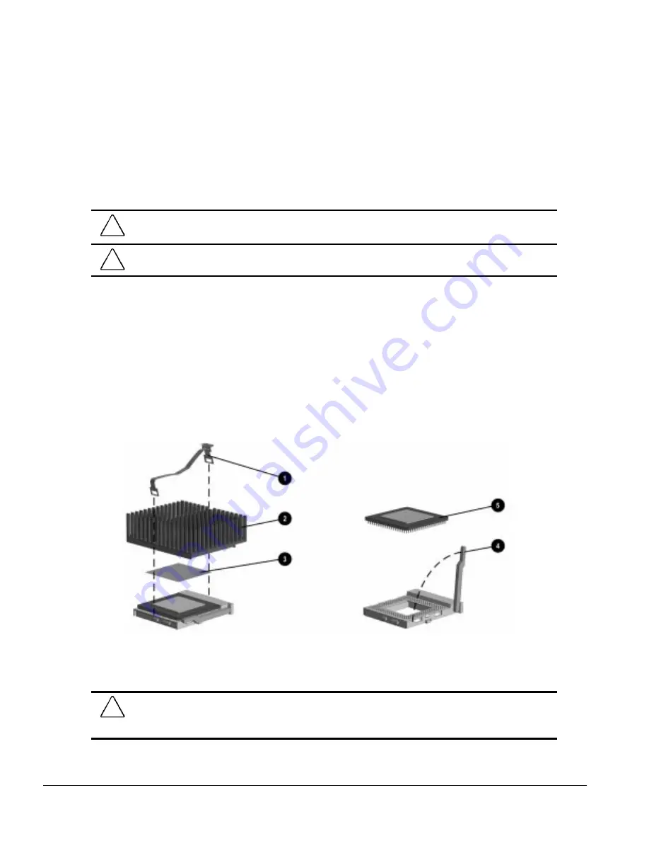
To remove the microprocessor from the Pentium system board, complete the following steps
1. Remove the access panel (Section 6.6.1).
2. Remove any cables attached to expansion boards on the riser assembly.
CAUTION:
When replacing the processor, you must release the heat sink retaining clip before you pull the
ZIF socket handle. The clip engages the processor socket to hold the heat sink in place.
!
WARNING:
To reduce the risk of personal injury from hot surfaces, allow the internal system components
to cool before touching.
3. Remove the riser brace (Section 6.7).
4. Remove the heat sink retaining clip
1
by pressing down on the clip’s extended tab until it
releases from the safety catch.
5. Lift the heat sink
2
off the processor.
6. Release the processor from the socket by pulling the handle on the ZIF socket out and upward
4
.
✎
The handle on the ZIF socket in the picture may not look identical to the one on the
computer. All handle types perform the same function.
7. Lift the processor
5
out of the socket.
Figure 6-14.
Removing the Microprocessor from the System Board
✎
For the location of the processor socket on the system board, see Chapter 7.
CAUTION:
When replacing the processor, be sure the clipped corner of the processor (location of Pin 1) is
aligned with the triangular area of the ZIF socket (marked * on the system board). Failure to do so could
result in burning out both the processor and the system board.
Summary of Contents for 244100-005 - Deskpro 2000 - 16 MB RAM
Page 2: ...278041 001 278785 002 ...
Page 4: ...CPS ...
Page 67: ...3 2 Illustrated Parts Catalog 3 1 System Unit Figure 3 2 System Unit Desktop ...
Page 69: ...3 4 Illustrated Parts Catalog Figure 3 3 System Unit Minitower ...
Page 71: ...3 6 Illustrated Parts Catalog 3 2 Mass Storage Devices Figure 3 4 Mass Storage Devices ...
Page 73: ...3 8 Illustrated Parts Catalog 3 3 Cables Figure 3 5 Cables ...
Page 75: ...3 10 Illustrated Parts Catalog 3 4 Standard and Optional Boards Figure 3 6 Optional Boards ...
Page 81: ...3 16 Illustrated Parts Catalog 3 6 Monitors Figure 3 9 Monitors ...


