5-16
Removal and Replacement Procedures - Desktop
Pentium II System Board
To remove the microprocessor from the Pentium II system board, complete the following steps: :
1. Remove the system unit cover (Section 5.6).
2. Remove any expansion boards that might block access to the microprocessor (Section 5.8.1
and/or 5.8.2).
3. Remove the front bezel (Section 5.14.1).
4. Remove the drive cage (Section 5.17).
!
WARNING:
To avoid the risk of personal injury from hot surfaces, allow the internal system components
to cool before touching.
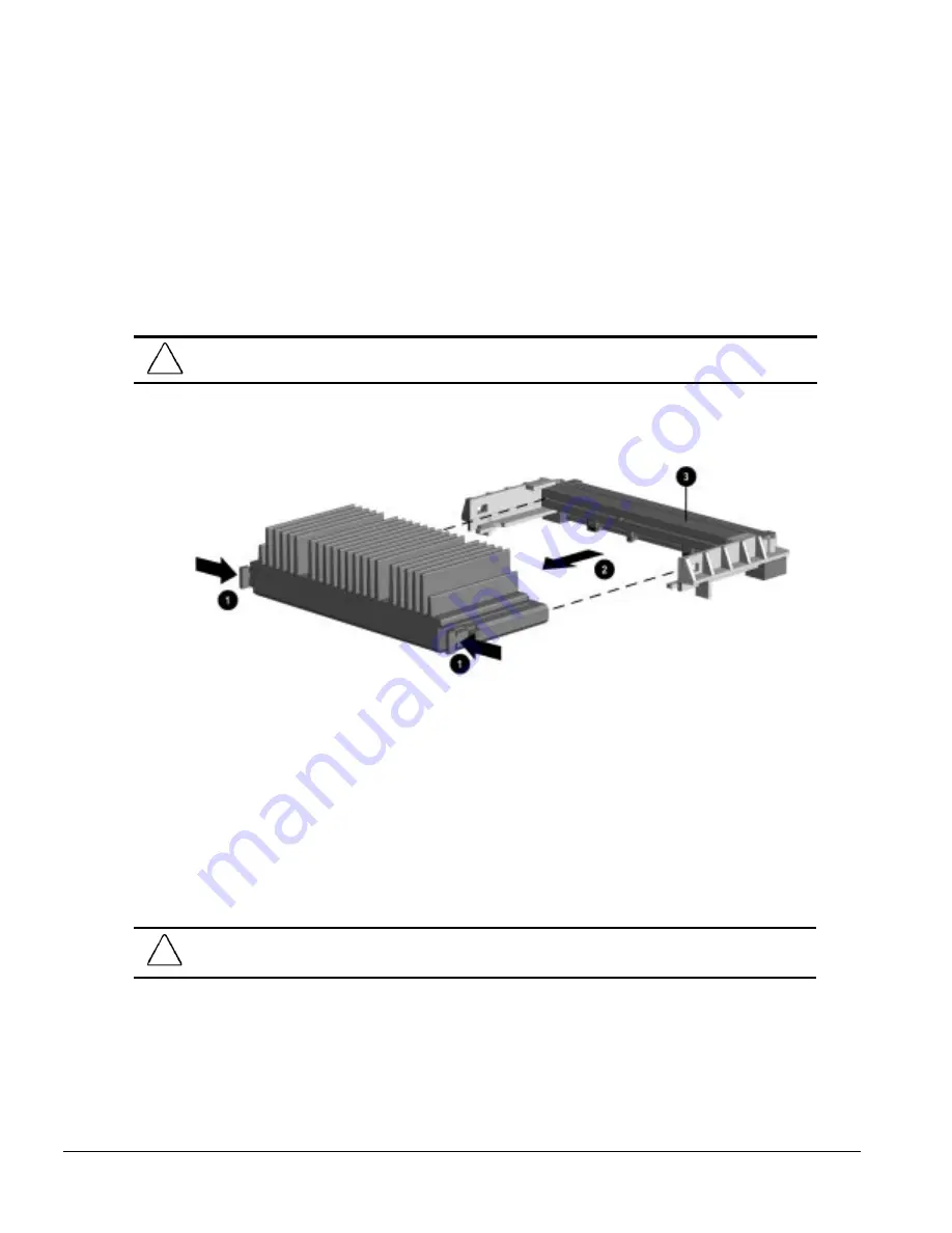
5. Press in on the processor module release latches
1
until they lock in the released position.
6. Pull the processor module away from the connector
2
.
Figure 5-14.
Removing the Microprocessor from the Pentium II System Board
✎
For the location of the processor connector on the Pentium II system board, see Chapter 7.
7. Lift the processor module to remove it from the guide rails and the machine.
To install the Pentium II processor, complete the following steps:
1. Ensure that the release latches are locked in the released position.
2. Set the Pentium II processor on the guide rails.
3. Slide the processor along the rails until it is firmly seated in the connector.
CAUTION:
Do not use the connector pins or pin guard
3
as a handle. Even with the guard in place, the
pins could bend, causing shorts that would damage the processor.
4. Pull out on the release latches until they snap into place.
5. Replace the drive cage.
6. Replace the front bezel.
7. Replace any expansion boards that were removed.
Summary of Contents for 244100-005 - Deskpro 2000 - 16 MB RAM
Page 2: ...278041 001 278785 002 ...
Page 4: ...CPS ...
Page 67: ...3 2 Illustrated Parts Catalog 3 1 System Unit Figure 3 2 System Unit Desktop ...
Page 69: ...3 4 Illustrated Parts Catalog Figure 3 3 System Unit Minitower ...
Page 71: ...3 6 Illustrated Parts Catalog 3 2 Mass Storage Devices Figure 3 4 Mass Storage Devices ...
Page 73: ...3 8 Illustrated Parts Catalog 3 3 Cables Figure 3 5 Cables ...
Page 75: ...3 10 Illustrated Parts Catalog 3 4 Standard and Optional Boards Figure 3 6 Optional Boards ...
Page 81: ...3 16 Illustrated Parts Catalog 3 6 Monitors Figure 3 9 Monitors ...


