background image

Figure 9

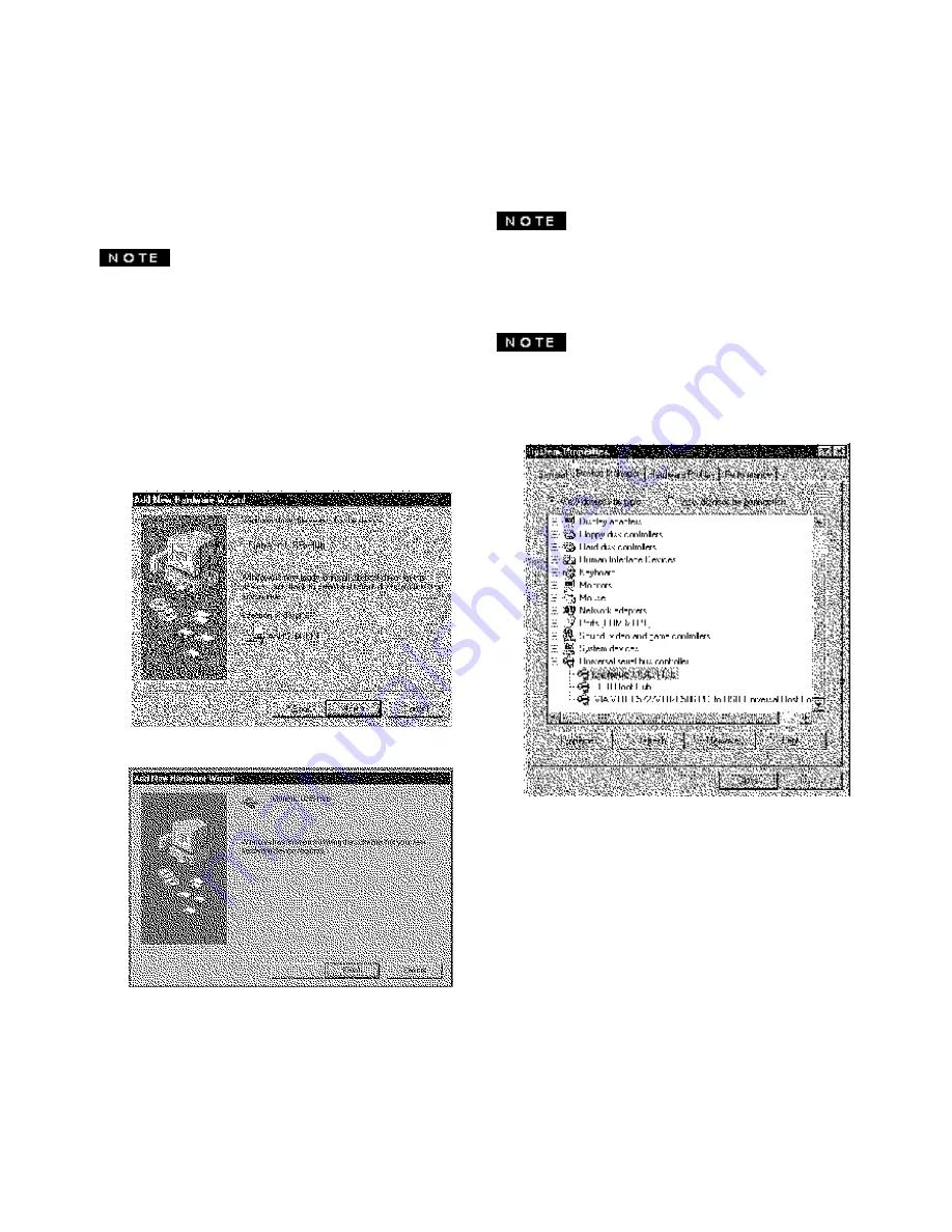
If the ! mark appears with  “Generic USB HUB”, then
enumeration was unsuccessful.  Select  “Generic USB
HUB” marked with ! mark and click “Remove” and
“Refresh”.  After that, the enumeration is automatically
started.

The enumeration of USB HUB may be necessary for
each USB   port on the computer.

Figure 7

3.4

Installation of USB Function

The following procedure permits your computer to recog-
nize or "enumerate"(A USB term) the USB HUB.

1.

Power on the display monitor and then the com-
puter.

2.

Start "Enumeration" from the Windows

®

 Desktop.

• During the enumeration of USB Hub, connect the key-

board and mouse, to the computer and not to the down-
stream ports on the display monitor.  After the enumera-
tion, the keyboard and mouse can be used by connecting
to the downstream ports, if they are USB-compliant.

• Do not unplug the USB cable during the enumerations.

(1) Connect the computer and the display monitor with the

included USB cable.  Figure 7 will appear.

(2) Click “Next” on Figure 7 to get Figure 8.
(3) Click “Finish” on Figure 8  to complete the enumeration

of USB HUB.

You can  confirm that the USB HUB is successfully enumer-
ated with the following method.

Open “Device Manager” tab in “System” property
under “Control Panel”.  Confirm that  “Generic USB
HUB” is listed in “Universal Serial Bus Controller”.  If
you can’t confirm it, re-enumerate the USB HUB
again by following (a) or (b).

Figure 8

(a) Disconnect and connect the USB cable to the

upstream port of the display monitor.

(b) Cycle power of the display monitor off then on.

Summary of Contents for 230538-001 - P 1210 - 22" CRT Display

Page 1: ...b Compaq P1220 July 2001...

Page 2: ...nnector hoods in order to maintain compliance with FCC Rules and Regulations DeclarationofConformityfor products marked with the FCC logo United States only This device complies with Part 15 of the FC...

Page 3: ...ments of the EPA Energy Star program As an Energy Star Partner Compaq Computer Corporation has determined that this product meets the Energy Star guidelines for energy efficiency Specificdetailsonusin...

Page 4: ...2 PART NAME 1 5 2 1 Control Names 1 5 2 2 Function 1 5 3 INSTALLATION AND CONNECTION 1 6 3 1 AC Power Connection 1 6 3 2 Signal Cable Connection 1 6 3 2 1 Connection to VGA Compatible System 1 6 3 2...

Page 5: ...for pre pro grammed screen display standards and is also capable of storing additional user adjustment parameters The monitor has AUTO SIZE ADJUST function to optimize the size and distortion for Non...

Page 6: ...or color purity Avoidcoveringtheslotsoropeningsofthemonitor Allow adequateventilationaroundthemonitorsotheheatfrom the monitor can properly dissipate Avoid putting the monitor into any enclosure that...

Page 7: ...Unpacking After you unpack the box you should have all of the items indicatedinFigure1 Savetheboxandpackingmaterials in case you transport the monitor Figure 1 1 Color Monitor 2 AC Power Cord 3 Signa...

Page 8: ...r 10 USB DOWNSTREAM PORTS To connect to USB equippedperipherals e g USBcameras keyboards printers etc 2 2 Function 1 POWER SWITCH A push on push off switch for AC power 2 POWER ON INDICATOR This indic...

Page 9: ...ctor is provided for compatible analog RGB outputs from your computer 3 2 1 Connection to VGA Compatible System Figure5showstheSC B110cableconnectiontotheVideo Graphics Array VGA port 1 Power off both...

Page 10: ...puters Figure 6 shows the connection to two computers Refer to clause 3 2 1 for the connection procedure 3 3 USB System Basic Application The Computer is required to have Windows 98 or later installed...

Page 11: ...am ports on the display monitor After the enumera tion thekeyboardandmousecanbeusedbyconnecting to the downstream ports if they are USB compliant Do not unplug the USB cable during the enumerations 1...

Page 12: ...has an OSD On Screen Display function The following procedure shows how to adjust the screen using the OSD function 4 1 How to adjust the screen If you don t press any button for the time set at OSD...

Page 13: ...ORY PRESET to restore to the factory preset level B Press and buttons together to restore to the factory preset level C Set data does not change by the change of the signal timing 4 2 Adjustment Items...

Page 14: ...If a non Factory Preset timing is used FACTORY PRESET does not work X Available...

Page 15: ...nals Monitormaynotbeabletogetfull screenimagedependon signal Inthiscase pleaseselectotherresolution orother vertical refresh timing Make sure you wait a few seconds after adjusting the size of the ima...

Page 16: ...le stabilization filaments Damper Wires which are required for all aperturegrilleCRTs A buzzing sound when power on A brief vibration or hum sound that is heard just after power up is normal This is c...

Page 17: ...video signal at 9300K 8MPCD Horizontal or 2 0 sec typ Vertical or 400 sec typ DISPLAY SIZE 396mm x 297mm typ s ratio 4 3 371mm x 297mm typ ratio 5 4 COLOR 5000K 9300K POWER SOURCE AC100 120 220 240V...

Page 18: ...4 VERTICALSYNC VCLK 15 SCL DDC DISPLAY DATA CHANNEL SDA SERIAL DATA SCL SERIAL CLOCK NC NO CONNECTION NOTE Available on Input A No connection on Input B For P1220 only 7 APPENDIX DDC DISPLAY DATA CHAN...

Reviews: