860452168
Instruction Sheet
www.commscope.com
Page 16 of 21
Notes
:
•
It is recommended that splicing operations be performed on a work surface outside the shelf, prior to tray
installation. Approximately 5 feet (1.5 meters) of buffer tube length should be prepared with an additional 3
feet (1 meter) of fiber exposed for splicing. Slack buffer tube length should allow tray to be removed from
shelf for subsequent adds, moves or repairs.
•
It is recommended that buffer tubes be brought into shelf through upper cable entry openings at rear to
provide maximum clearance possible between trays and fiber.
•
Bundle buffer tubes together with hook-and-loop fasteners or cable ties within interior of shelf to protect
adapter panel pigtails.
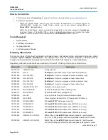
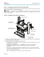
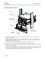
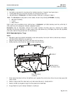
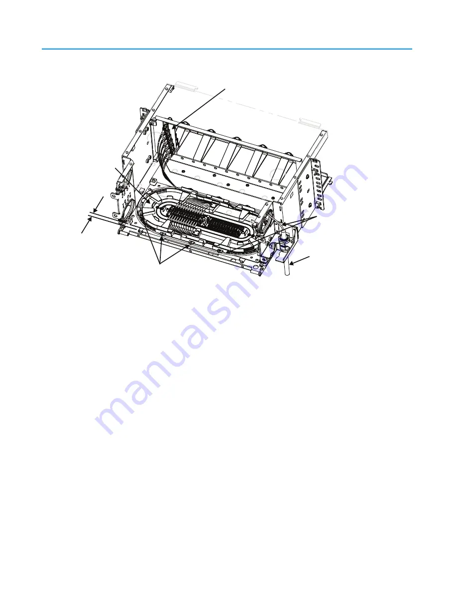
5. Using a lint-free wipe and isopropyl alcohol, clean area where splice tray is to be located.
6. Peel off paper backing from splice tray. Center over shelf chassis floor so that tray butts up against rear-
most sheet metal edge, approximately 0.25 inch (6mm) from rear of sliding mechanism and press down
firmly to adhere tray.
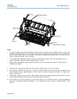
7. Route buffer tube(s) to tray, as shown above. Buffer tube slack shall be spooled around perimeter of tray
and restrained with cable ties at tie-down points provided, as necessary.
8.
Each splice tray will accommodate up to 48 fusion splices. If more splice capacity is required, additional
trays may be stacked and attached together. Up to eight trays may be used for a
total
capacity of 384
splices.
Cable ties
Splice tray
.25”
(6mm)
Adapter panel
Buffer tube
OSP or
indoor/outdoor cable

