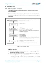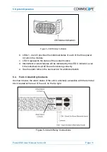
5
.
System Operation
Page 18
PowerShift User Manual Version B
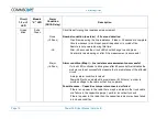
Circuit
1, 2 or 3
LED
Module
“X” LED
Alarm
Condition
(GUI & Relay)
Description
Note
: A red blink circuit LED can occur if the input power is cycled off and
immediately back on, and there is no load (radio) connected to the circuit. In this
case the capacitive jumper retains a small amount of voltage, and the module
must allow it to discharge down before it can start the line resistance
measurement. Allow 1-2 minutes for the discharge to occur, the LED will then
change to green blink to indicate the line resistance measurement is in
progress.


