


507868-02P
Page 34 of 48
Issue 1922
Electrical
ELECTROSTATIC DISCHARGE (ESD)
Precautions and Procedures
Electrostatic discharge can affect electronic components.
Take precautions during furnace installation and service
to protect the furnace’s electronic controls. Precautions
will help to avoid control exposure to electrostatic
discharge by putting the furnace, the control and the
technician at the same electrostatic potential. Neutralize
electrostatic charge by touching hand and all tools on
an unpainted unit surface, such as the gas valve or
blower deck, before performing any service procedure.
CAUTION
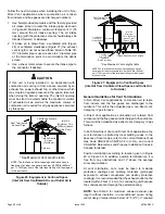
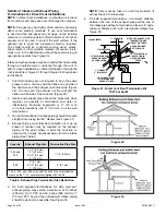
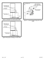
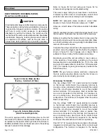
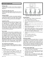
Figure 55. Interior Make-Up Box
(Factory - Installed Left Side)
Figure 56. Exterior Make-Up Box
(Field Provided Right Side)
The unit is equipped with a field makeup box on the left
hand side of the cabinet. A field-provided make-up box can
be installed on the exterior of the right side of the furnace to
facilitate installation. Secure the excess wire to the existing
harness to protect it from damage.
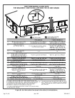
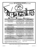
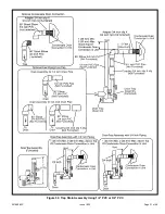
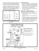
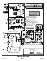
Refer to Figure 58 for field wiring and Figure 59 for
schematic wiring diagram and troubleshooting.
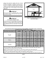
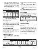
The power supply wiring must meet Class I restrictions.
Protected by either a fuse or circuit breaker, select circuit
protection and wire size according to unit nameplate.
NOTE:
Unit nameplate states maximum current draw.
Maximum Over-Current Protection allowed is 15 AMP.
Holes are on both sides of the furnace cabinet to facilitate
wiring.
Install a separate (properly sized) disconnect switch near
the furnace so that power can be turned off for servicing.
Before connecting the thermostat check to make sure the
wires will be long enough for servicing at a later date. Make
sure that thermostat wire is long enough to facilitate future
removal of blower for service.
Complete the wiring connections to the equipment. Use the
provided unit wiring diagram and the field wiring diagram
shown in Figure 58. Use 18 gauge wire or larger that is
suitable for Class II rating for thermostat connections.
Electrically ground the unit according to local codes or,
in the absence of local codes, according to the current
National Electric Code (ANSI/HFPA No. 70) for the USA
and current Canadian Electric Code Part 1 (CSA standard
C22.1) for Canada. A green ground wire is provided in the
field makeup box.
NOTE:
The gas furnace contains electronic components
that are polarity sensitive. Make sure that the furnace is
wired correctly and is properly grounded.
Accessory Terminals
One line voltage “EAC” 1/4” spade terminal is provided
on the furnace control board. Any accessory rated up to
one amp can be connected to this terminal with the neutral
leg of the circuit being connected to one of the provided
neutral terminals. If an accessory rated at greater than
one amp is connected to this terminal, it is necessary to
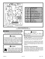
use an external relay. See Figure 60 for control board
configuration. This terminal is energized when the indoor
blower is operating.
One line voltage “HUM” 1/4” spade terminal is provided
on the furnace control board. Any humidifier rated up to
one amp can be connected to this terminal with the neutral
leg of the circuit being connected to one of the provided
neutral terminals. If a humidifier rated at greater than
one amp is connected to this terminal, it is necessary to
use an external relay. See Figure 60 for control board
configuration. This terminal is energized in the heating
mode when the combustion air inducer is operating.
One 24V “H” 1/4” spade terminal is provided on the furnace
integrated control board. See Figure 60 for control board
configuration. The terminal is energized in the heating


