background image

507868-02P

Page 37 of 48

Issue 1922

Unit Start-Up

FOR YOUR SAFETY READ BEFORE OPERATING

Do not use this furnace if any part has been underwater. 

A  flood-damaged  furnace  is  extremely  dangerous. 

Attempts to use the furnace can result in fire or explosion. 

Immediately call a qualified service technician to inspect 

the  furnace  and  to  replace  all  gas  controls,  control 

system parts, and electrical parts that have been wet or 

to replace the furnace, if deemed necessary.

 WARNING

Danger of explosion. Can cause injury or 

product  or  property  damage.  Should  the 

gas supply fail to shut off or if overheating 

occurs, shut off the gas valve to the furnace 

before shutting off the electrical power. 

 WARNING

Before  attempting  to  perform  any  service  or 

maintenance, turn the electrical power to unit OFF at 

disconnect switch.

 CAUTION

BEFORE LIGHTING

 the unit, smell all around the furnace 

area for gas. Be sure to smell next to the floor because 

some gas is heavier than air and will settle on the floor.

The gas valve on the unit is equipped with a gas control 

switch (lever). Use only your hand to move switch. Never 

use tools. If the switch will not move by hand, do not try to 

repair it. Force or attempted repair may result in a fire or 

explosion.

Placing the Furnace into Operation

This  furnace  is  equipped  with  an  automatic  hot  surface 

ignition system. Do not attempt to manually light burners 

on this furnace. Each time the thermostat calls for heat, the 

burners will automatically light. The ignitor does not get hot 

when there is no call for heat on these units.

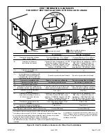
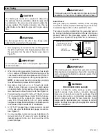
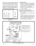
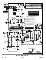
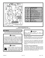
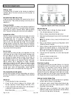
Figure 60. Integrated Control

(Automatic Hot Surface Ignition System)

Terminal Designations

120 HUM

Humidifier (120 VAC)

LINE

Input (120 VAC)

XFMR

Transformer (120 VAC)

CIRC

Indoor Blower (120 VAC)

EAC

Electronic Air Cleaner (120 VAC)

COOL

Blower - Cooling Speed (24 VAC)

HEAT

Blower - Heating Speed (24 VAC)

FAN

Blower - Fan Speed (24 VAC)

PARK

Dead terminals to park all speed taps

NEUTRALS

Neutral Terminals (120 VAC)

FS

Flame Sense

24 COM

Common (24 VAC)

HUM 24

Humidifier (24 VAC)

Summary of Contents for GDD92C

Page 1: ...or loss of life Installation and service must be performed by a licensed professional installer or equivalent service agency or the gas supplier WARNING As with any mechanical equipment personal injur...

Page 2: ...507868 02P Page 2 of 48 Issue 1922 Unit Dimensions Capacity A B C in mm in mm in mm 045 B3 070 B3 17 1 2 446 16 3 8 416 16 406 090 C4 21 533 19 7 8 504 19 1 2 495...

Page 3: ...Heating Compartment Access Panel Blower Access Panel Cold End Header Box Control Box includes integrated control transformer and door switch Blower Assembly Bag Assemblies Cabinet Blower Deck Heat Ex...

Page 4: ...aded street elbow Check equipment for shipping damage If you find any damage immediately contact the last carrier Please refer to specification sheets for available accessories Safety Information DANG...

Page 5: ...must be equipped to prevent operation of either the heating or the cooling unit unless it is in the full HEAT or COOL setting When installed this furnace must be electrically grounded according to lo...

Page 6: ...re drafts might blow directly into it This could cause improper combustion and unsafe operation When the furnace is installed in a non direct vent applications do not block the furnace combustion air...

Page 7: ...ombustion and ventilation depend largely on whether the furnace is installed in an unconfined or a confined space Unconfined Space An unconfined space is an area such as a basement or large equipment...

Page 8: ...n of rectangular air ducts shall be no less than 3 inches 75 mm In calculating free area the blocking effect of louvers grilles or screens must be considered If the design and free area of protective...

Page 9: ...ined Space all Air from Outside Shipping Bolt Removal Units with 1 2 hp and 3 4 hp blower motors are equipped with three flexible legs and one rigid leg The rigid leg is equipped with a shipping bolt...

Page 10: ...Do not drag the unit across the floor in the downflow position Floor and furnace flange damage will result Refer to Figure 14 for clearances in downflow applications Improper installation of the furna...

Page 11: ...2 After opening is cut set the combustible flooring base into opening 3 Check fiberglass strips on the combustible flooring base to make sure they are properly glued and positioned 4 Lower supply air...

Page 12: ...external static pressure which exceeds 0 5 inches w c Operation at these conditions may result in improper limit operation Supply Air Plenum If the furnace is installed without a cooling coil a remov...

Page 13: ...ces of ignition Do not use excessive amounts of solvent cement when making joints Good ventilation should be maintained to reduce fire hazard and to minimize breathing of solvent vapors Avoid contact...

Page 14: ...s Termination kits 44W92 and 44W93 are approved for use in Canadian installations to meet CSAB149 The 44W92 Concentric kit is provided with a 1 1 2 accelerator which must be installed on the exhaust o...

Page 15: ...condition 3 Close all building doors and windows and all doors between the space in which the appliances remaining connected to the common venting system are located and other spaces of the building...

Page 16: ...om outdoors and flue gases are discharged outdoors Intake and exhaust pipe sizing Size pipe according to Table 6 and Table 7A through Table 7B Table 6 lists the minimum vent pipe lengths permitted Tab...

Page 17: ...13 97 97 78 8 26 11 60 45 n a 92 92 73 9 21 n a 55 40 87 87 68 10 16 50 35 82 82 63 Concentric Termination Elevation 0 10 000 ft Number of 90 Elbows Used 1 1 2 Pipe 2 Pipe 2 1 2 Pipe 3 Pipe Model Mode...

Page 18: ...60 67 67 48 10 6 40 55 62 62 43 NOTE Additional vent pipe and elbows used to terminate the vent pipe outside the structure must be included in the total vent length calculation Figure 23 Typical Exhau...

Page 19: ...the furnace from the surrounding space the indoor air quality must be considered Guidelines listed in Combustion Dilution and Ventilation Air section must be followed Follow the next two steps when i...

Page 20: ...r to Outside Roof Terminated Exhaust Pipe Furnace Ventilation Louvers Crawl Space Intake Debris Screen Provided Inlet Air Minimum 12 in 305mm above Crawl Space Floor Coupling or 3 in to 2 in Transitio...

Page 21: ...n in Unconditioned Space for Winter Design Temperatures Single Stage High Efficiency Furnace Winter Design Temperatures1 F C Vent Pipe Diameter Unit Input Size 045 070 090 32 to 21 0 to 6 PVC 2 PP PVC...

Page 22: ...ce under veranda porch deck or balcony 12 Equal to or greater than soffit depth 3 feet 9m 12 3 feet 9m within a height 15 feet 4 5m above the meter regulator assembly 3 feet 9m 6 inches 152mm for appl...

Page 23: ...mm for appliances 10 000 pliances 10 000 Btuh 3kw and 50 000 pliances 50 000 Btuh 15kw 6 inches 152mm for appliances 10 000 Btuh 3kw 12 inches 305mm for appliances 10 000 Btuh 3kw and 100 000 Btuh 30k...

Page 24: ...tion is 3 76 mm on roof terminations and 6 152 mm on side wall terminations 3 On roof terminations the intake piping should terminate straight down using two 90 elbows see Figure 31 4 Exhaust piping m...

Page 25: ...t Furnished CLAMP INTAKE 12 305mm FIELD PROVIDED REDUCER MAY BE REQUIRED TO ADAPT DIFFERENT VENT PIPE SIZE TO TERMINATION Figure 36 Direct Vent Concentric Wall Termination DIRECT VENT CONCENTRIC WALL...

Page 26: ...n tee should be connected to the 2 or 3 PVC flue pipe as shown in the illustration Do not use an accelerator in applications that include an exhaust termination tee The accelerator is not required 2 A...

Page 27: ...pipe size must be done after the final elbow Figure 40 Non Direct Vent Roof Termination Kit UNCONDITIONED ATTIC SPACE 3 76MM OR 2 51MM PVC PROVIDE SUPPORT FOR EXHAUST LINES 12 305MM ABOVE AVE SNOW ACC...

Page 28: ...ermination Drain Trap assembled Figure 44 Kit 51W18 USA 15Z70 Canada Parts Identification and Assembly Exhaust from Furnace To Termination Exhaust from Furnace To Termination Kit 51W18 is shown Figure...

Page 29: ...ondensate drain Tubing must be 1 1 4 ODx1 ID and should be attached to the drain on the trap using a hose clamp Figure 47 Condensate Trap and Plug Locations 5 Figure 49 shows the furnace and evaporato...

Page 30: ...507868 02P Page 30 of 48 Issue 1922 Figure 49 Evaporator Coil Using a Separate Drain Figure 50 Evaporator Coil Using a Common Drain Figure 51 Condensate Trap with Optional Overflow Switch...

Page 31: ...507868 02P Page 31 of 48 Issue 1922 Figure 52 Trap Drain Assembly Using 1 2 PVC or 3 4 PVC...

Page 32: ...ip leg in vertical pipe runs to serve as a trap for sediment or condensate 5 A 1 8 N P T plugged tap or pressure post is located on the gas valve to facilitate test gauge connection See Figure 53 6 In...

Page 33: ...4 118 3 34 110 3 11 103 2 92 1 25 4 1 049 26 645 680 19 25 465 13 17 375 10 62 320 9 06 285 8 07 260 7 36 240 6 80 220 6 23 205 5 80 195 5 52 1 1 4 31 75 1 380 35 052 1400 39 64 950 26 90 770 21 80 66...

Page 34: ...long enough to facilitate future removal of blower for service Complete the wiring connections to the equipment Use the provided unit wiring diagram and the field wiring diagram shown in Figure 58 Us...

Page 35: ...ly on the heating speed when there is no cooling or heating demand See Table 16 for allowable continuous circulation speeds 2 When the furnace is running in the heating mode the indoor blower will run...

Page 36: ...507868 02P Page 36 of 48 Issue 1922 045B3 070B3 090C4 Figure 59 Typical Wiring Diagram...

Page 37: ...next to the floor because some gas is heavier than air and will settle on the floor The gas valve on the unit is equipped with a gas control switch lever Use only your hand to move switch Never use to...

Page 38: ...low the gas supplier s instructions If you do not smell gas go to next step 8 Move gas valve switch to ON See Figure 61 9 Replace the heating compartment access panel 10 Turn on all electrical power t...

Page 39: ...rt unit and allow 5 minutes for unit to reach steady state 3 While waiting for the unit to stabilize observe the flame Flame should be stable and should not lift from burner Natural gas should burn bl...

Page 40: ...Orifice Kit All 11K50 73W80 51W01 11K45 Conversion requires installation of a gas valve regulator spring which is provided with the gas conversion Kit LP Kits include low line pressure switch Pressur...

Page 41: ...2 Visually inspect the venting system for proper size and horizontal pitch Determine there is no blockage or restriction leakage corrosion or other deficiencies which could cause an unsafe condition 3...

Page 42: ...nticipator setting if adjustable according to the amp draw listed on the wiring diagram that is attached to the unit Electrical 1 Check all wiring for loose connections 2 Check for the correct voltage...

Page 43: ...65 276 1140 202 860 109 700 73 0 20 1345 360 1240 285 1090 208 810 119 645 79 0 30 1325 371 1215 291 1060 218 770 124 590 84 0 40 1295 380 1175 302 1025 228 710 132 530 91 0 50 1260 392 1135 318 985 2...

Page 44: ...nsure proper furnace operation Table 3 lists recommended filter sizes Exhaust and Air Intake Pipes Check the exhaust and air intake pipes and all connections for tightness and to make sure there is no...

Page 45: ...abinet Remove two screws from blower rail which secure bottom heat exchanger flange Remove heat exchanger from furnace cabinet 17 Back wash heat exchanger with soapy water solution or steam If steam i...

Page 46: ...ent will be displayed first LED off for 3 sec then next error code is displayed etc To clear error codes depress and hold button longer than 5 seconds Cleaning the Burner Assembly 1 Turn off electrica...

Page 47: ...blems detected during the inspection may make it necessary to temporarily shut down the furnace until the items can be repaired or replaced Instruct the homeowners to pay attention to their furnace Si...

Page 48: ...height of eight 8 feet above grade directly in line with the exhaust vent terminal for the horizontally vented gas fueled heating appliance or equipment The sign shall read in print size no less than...

Reviews: