background image

Atena Easy Addressable Fire Alarm Panel – Installation and Programming Manual 


28 

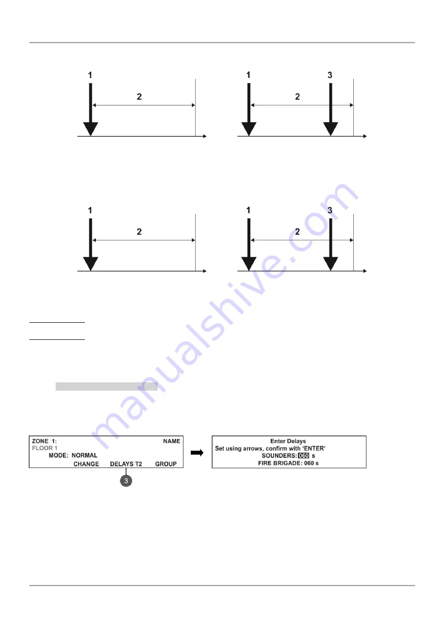
Examples for 2 DEVICES action mode operation: 


– An incoming alarm signal from Detector 1 and zone reset; 

– Awaiting for a second alarm signal from other detector in the zone – Pre Alarm Mode; 

– Second alarm signal from Detector 2 in the zone. 


Examples for DOUBLE action mode operation: 


– An incoming alarm signal from Detector 1 and zone reset; 

– Awaiting for a second alarm signal from the same detector in the zone – Pre Alarm Mode; 

– Second alarm signal from Detector 1 in the zone. 


EXAMPLES 1, 3: In this case the fire panel will not activate the sounders and the signalization on the front panel 
because during time interval 2 no second alarm signal is generated. 
EXAMPLES 2, 4: In this case the fire panel will activate the sounders and the signalization on the front panel because 
during time interval 2, two alarm signals are generated. 


After RESETTING of the panel, the events FIRE and PRE ALARM 

are cleared, and LED ‘General Fire’ light off. 


7.2.7 Programming Delays 

Т2 

Т2 represents times for individual delay setting for activation of FIRE output and the sounders outputs SND1 and 
SND2. For details see also APPENDIX D 

– “Two steps of alarming” algorithm. 

 
To enter in the submenu for DELAY 

Т2 setting, press button (3) DELAY T2 from the zone parameters programming 

screen. 


In the 

SOUNDERS 

field set the time delay for sounders (SND1 and SND2) outputs activation. The time delay 

can be in range from 0 up to 540 seconds.  


In the 

FIRE BRIGADE 

field set the time delay for FIRE output activation. The time delay can be in range from 

0 up to 540 seconds. 

 
In case of activation of more than one zone, the delays to the outputs are caused by the zone with shorter delays. 
By default a 60 seconds time delays T2 are set. 
The editing value is blinking. Set the time delays using the navigation buttons: up (increasing) and down (decreasing) 
arrows to change the value, and left and right arrows to move over the fields. 
The set time delays T2 are confirmed with the ENTER button. 

Time 

Time 

5 min 

5 min 

EXAMPLE 1 

EXAMPLE 2 

D 1 

D 1 

D 2 

Time 

Time 

5 min 

5 min 

EXAMPLE 3 

EXAMPLE 4 

D 1 

D 1 

D 1 

Summary of Contents for 41CPE012

Page 1: ...duct use and function and information on the limitations as to liability of the manufacturer The entire manual should be carefully read The information in this manual is a subject to change without notice ATENA EASY 41CPE012EN METALLIC ADDRESSABLE PANEL INSTALLATION MANUAL ...

Page 2: ... from Computer 16 3 3 2 Firmware Update from USB Drive 17 3 3 3 Copying Image File from the Panel to USB Drive 17 4 FULL HARDWARE RESET 17 5 PROGRAMMING OF ATENA EASY FIRE ALARM PANEL 18 5 1 General Information for Programming and Operation 18 5 2 Codes and Access Levels 18 6 DESCRIPTION OF THE OPERATION MODES 20 6 1 Review of Alarm Events 20 6 2 Review of Fault Events 20 6 3 Review of Disablement...

Page 3: ...u 48 7 9 Software Revision 48 7 10 Network 48 7 10 1 Network Settings 48 7 10 2 Panels Settings 49 7 11 Active Isolators Menu 49 7 12 Access Level 1 49 APPENDIX А 50 APPENDIX B 52 APPENDIX C 52 APPENDIX D 53 APPENDIX E 54 DoP No 002 Comelit Group S p A Via Don Arrigoni 5 24020 Rovetta S Lorenzo BG Italy tel 39 0346 750 011 fax 39 0346 71436 email info comelit it export department comelit it EN 54 ...

Page 4: ... rows x 40 symbols functional buttons and system status LED indication Separate access level passwords provide access to the functions of the panel The fire alarm panel is designed on module structure as in the metal cabinet there are provided additional places for mounting of a second loop controller for Loop 2 Loop 1 is built in the main PCB a communication module and redundant network module Th...

Page 5: ...rding the requirements of EN54 2 4 Metal box cabinet for wall mounting bottom 306х412х81mm and cover 310х416mm 1 2 2 Possible Hardware Configurations Minimal Configuration o Control panel main PCB with one built in loop controller o Indication indication PCB with mounted LCD module o Power supply source Maximal Configuration o Control panel main PCB with one built in loop controller o Indication i...

Page 6: ...DC Max loading capacity of outputs FIRE FAULT and EXT 300 mA DC Max total loading capacity sum of the four mentioned above 2 0 A DC Programmable relay outputs 15A 24VDC Consumption From the main power supply in standby mode o For a minimum configuration 60 mA AC o With mounted second loop controller 65 mA AC From the backup power supply in FAULT mode and generated message AC loss o For a minimum c...

Page 7: ...ring Open the front cover and disconnect the flat indication cable and the earthling point Figure 2 Figure 1 Figure 2 Remove the front cover as dismount the side hinges Figure 3 Figure 3 Choose inlets for the main power supply cable loops sounders control devices etc Remove the metal cap element just from those holes for cable running Figure 4 Figure 4 Elements of the metal bottom а View from abov...

Page 8: ...aper label is placed in a special opening on the inner side of the indicator PCB over the flat cable for the indication 2 LED indication for the used zones 3 Letters and digits LCD module 4х40 4 Functional digits buttons 5 Control and navigation buttons Figure 5 1 Description of system status LED indication LED Indication Description GENERAL FIRE red Lights on permanently in case of fire alarm eve...

Page 9: ...entry Changing of value or parameter status 5 Description of control and navigation buttons Button Action Description Silence Buzzer The button is active at access levels 1 2 and 3 The button functionality is deactivation of the internal buzzer Silence Sounders The button is active at access levels 2 and 3 The button functionality is deactivation of the sounders in case of fire alarm event After p...

Page 10: ...g of a communication module 7 Place for mounting of redundant network module 2 2 3 Description of the main PCB control panel Figure 7 Main PCB of the Atena Easy fire alarm panel Description of the terminal row left to right RELAY 1 4 Programmable volt free change over relay contacts each 24VDC 15A Each relay has one NO normal open and one NC normal closed contact with common lead on a terminal Whe...

Page 11: ...B connector for firmware update of the main microprocessor via PC or USB flash drive suitable also for programming via AtenaProg software BATT Connector with wires red and black for connection to the accumulator battery The type of connection is according the battery terminals to every cable shoe is added a separate cable lug connector Ø5mm M5 Restore Defaults Jumper for full hardware reset of the...

Page 12: ...st not exceed 0 5A Before connecting the last sounder in the circuit parallel to it must be added resistor 10k Figure 10 Connecting sounders to SND output 2 3 2 Connecting of Signaling Devices To every monitored output FAULT EXT and FIRE could be connected signaling and other control devices Figure 11 The maximal consumption of the devices should not exceed 0 3А Before connecting the last device i...

Page 13: ...hown on Figure 13 The maximum current consumption of the devices in the communication line is Imax 500mA If the consumption exceeds this value an over load protection would be turned on Figure 13 Connecting of detectors to a loop controller In the configuration of addressable fire alarm panel Atena Easy could be mounted a second loop controller as a separate module see Figure 14 ATTENTION Do not a...

Page 14: ...ain control panel Connect the battery leads to the accumulator terminal as observe the polarity see Figure 17 The battery cannot power up the panel before the mains supply has been switched on The charging of the accumulator battery is done at maximum current I 2A and charging voltage U 13 65V Main Power Source Fuse 4А Type glass time delay Figure 17 Connecting the accumulator battery Black Red Ac...

Page 15: ...B9 DIN5 Kafka printer type connectors as shown on Figure 18 Before printing access levels 2 and 3 make sure that the heat printer is connected to the PRINTER interface connector on the main PCB and the printer is powered on 2 7 Connecting a Network Module supported for Soft Revision 2 8 and higher The addressable fire alarm panel Atena Easy is designed with option for connection in a Ethernet netw...

Page 16: ... the editable fields confirmation of entered parameters cancelation of entered parameters and step back in the menu programming structure Specialized buttons for User operation Silence buzzer Silence sounders Reset Evacuation General test of the LEDs buzzer and screen The detailed description of all buttons on the front panel is presented in item 2 2 1 5 page 9 The detailed description of Maintena...

Page 17: ...e screen as the software revision is displayed on the right side for example 0 AtenaEasy AtenaEasy2_0 BIN v 2 00 Scroll through the listed files using the buttons with up and down arrows the currently selected file is blinking Select the file and press Enter button The panel starts uploading the file from the USB drive to the external Flash memory of the panel The running process is displayed with...

Page 18: ... the number of the first message Press the ENTER button to review some additional information for the respective message as data and time of occurring device address zone number or other according the trouble type The indication for the active ALARMS in the system is viewed with highest priority The addressable fire alarm panel Atena Easy supports different languages for the programming menus The ...

Page 19: ...rameter programming Addressing Menus for addressing devices Set address Setting an address for single devices Change address Changing device address Self addressing Automatic self addressing mode Autoaddressing Automatic mode for addressing devices by ID or isolator Panel outputs Parameter programming for the built in panel outputs SOUNDERS EXITING FIRE FAULT RELAY OUTPUTS General Settings General...

Page 20: ...ion for every of the alarm events For this select the number of the alarm message using up down arrow buttons the number of the selected event is blinking and press ENTER button On the screen is displayed information for the loop number and the address of the device sensed the alarm event At the bottom of the screen is displayed the day and time of occurring of the respective event Note that the a...

Page 21: ... go back to ALARMS mode and reviewing the alarm messages To review the DISABLED at active alarms and or faults in the system To exit the review fault events mode press CANCEL button 6 4 Review of Running Tests The messages for running tests are displayed with normal priority If no alarm or fault events or disablements are present and there are active tests in the system the TESTS mode is blinking ...

Page 22: ...ated input output is displayed after the address For example the screen displays message Loop Device Input Active L 1 Z 1 D 3 1 where after the address of the device is displayed and the number of the activated input of the module In the example the address of the module is 3 and the number of activated input is 1 The name of the input will be displayed at the end of the message see 7 3 6 In case ...

Page 23: ...r evacuation alert the user has to enter in sequence 6 9 Resetting the Panel The resetting of the panel s current state is available from access levels 2 and 3 after code entry The resetting function is used for initializing the panel and return to normal operation mode after alarm or fault restoring To reset the panel enter in sequence After resetting are cleared also all introduced earlier test ...

Page 24: ...s the installer to review and print the system events recorded in the panel memory log file The capacity of the panel memory log file is 10000 events The installer can clear also all panel s memory or to extract a list of events by date The menus are accessible from levels 2 and 3 After entering the menu the screen displays The following general information is displayed in the main screen of VIEW ...

Page 25: ...ance access level 2 7 1 4 Printing Events Attention To print the system events you have to connect printer to the PRINTER terminal on the main board Check your printer connection before entering this menu Use only printer models recommended from the manufacturer From the main screen of VIEW LOG menu press 4 PRINT button The screen displays two fields for setting a time interval for the extract Two...

Page 26: ...main screen of ZONES menu as the number of the zone is blinking Submenu 2 DEV VIEW The submenu shows information about the total number of the devices in the respective zone From the main screen of ZONES menu select a zone number and press button 2 A detailed list with address and name of the respective devices is displayed also The screen displays information about the total number of the devices...

Page 27: ...second row Use the left and right arrows to move the cursor The symbols small and capital letters and characters are set with the up and down arrows Confirm the entered name with ENTER button See also the APPENDIX B Table for text and symbols available for zone and device names 7 2 6 Zone Operation Modes For a zone can be set one operation mode NORMAL 2 DEVICES DOUBLE Every pressing of button 2 CH...

Page 28: ...ALARM are cleared and LED General Fire light off 7 2 7 Programming Delays Т2 Т2 represents times for individual delay setting for activation of FIRE output and the sounders outputs SND1 and SND2 For details see also APPENDIX D Two steps of alarming algorithm To enter in the submenu for DELAY Т2 setting press button 3 DELAY T2 from the zone parameters programming screen In the SOUNDERS field set th...

Page 29: ... configuration Example for the screen display after entering the menu The screen is divided in the following sections 1 Address of the device 2 Zone number 3 Loop number 4 System name of the device according its type 5 The current status of the device NEW The device is new in the system To save it press button 3 SAVE see item 7 3 2 NORMAL The device is in normal operation mode FAULT The device is ...

Page 30: ...utton 1 GO TO Note The panel automatically saves the new devices on the serial address The other types of addressing or changing the current set address are described in item 7 4 7 3 3 Deleting Devices Every loop device can be deleted from the system configuration Loop 1 or Loop 2 in the DEVICES SETUP menu To delete one or all devices from the respective loop configuration select the address of th...

Page 31: ...tus and press 3 FIX button The panel will ask if you want to fix the type of the selected device only button 2 THIS or all devices with wrong type button 3 ALL in the respective Loop number The exit is automatic to the main screen DEVICES SETUP as the fixed devices are displayed with status NORMAL 7 3 6 Programming of Device Parameters Attention Programming device type parameters is available only...

Page 32: ...tion mode Note Devices 41IOM010 41SAI000 and 41SAB000 have no LED indication for showing the communication with the panel In the setup menu of every device is introduced a system ID field with a unique 10 digit number the ID number of the device for identification in the system configuration Use the functional digit buttons to enter the respective submenus according the type of the selected device...

Page 33: ...setting menus 1 Enabling Disabling the operation of the thermal part of the detector Every pressing of the button changes alternatively the parameter 2 Setting the sensitivity level in DAY operation mode Normal Middle Low High Press the button until reaching the desired sensitivity level 3 Setting the sensitivity level in NIGHT operation mode Normal Middle Low High Press the button until reaching ...

Page 34: ...nnected sounders to the loop is up to 30 LOW Set in those cases when the number of the connected sounders to the loop is up to 60 Sounders 41SAI000 41SCI000 4 ON OFF TURN Press to switch on off the sound of the sounder when checking for double addresses or finding the place of installation 41SCI000 Wall mounted sounder and strobe with isolator Use the functional buttons to set the following specia...

Page 35: ...s mounted to bases 41SAB000 are assigned at separate addresses in the control panel To calculate the total consumption of the sounders in the loop and to define the proper sound level you can use the Table a below as fill in the number of the used sounders according their type Table 1 for calculation of the total consumption of the sounders in the loop with defined sound level and set ALARM and or...

Page 36: ... for the module s input CLASS CHANGE To use the class change function connect the terminals of a switch with normally open contacts to the module terminals SILENCE ALARM STROBE ON Use to disable the sounders in case of evacuation event for example when using the panel together with a separate Voice Evacuation System The sounders will be silent but their LED signalization will be active 41SAI000 an...

Page 37: ... case of disablement in the system SOUNDER ON Activation in case of sounder activation in the system RESET Activation in case of reset in the system EVACUATE Activation in case of evacuation event in the system EVACUATE ZONE GROUP Activation in case of Evacuation and Fire Alarm in the respective group SILENCE BUZZER Activation in case of silence buzzer in the system SILENCE ALARM Activation in cas...

Page 38: ...number of the module press MORE button again Use the functional buttons to set parameters for the inputs For the settings of the IN 1 2 3 4 refer to the submenu of 41IOM010 To associate IN 1 2 3 4 for operation in a group press button 2 GROUP in the screen of the respective input number In the editing field enter the group number using the up down arrow buttons 41IOM000 Module potential output The...

Page 39: ...ccess level 3 This menu allows the installer to set or change the device address or to perform self addressing or auto addressing procedure The type of addressing depends on the installer s preferences and the system capacity and configuration The installer can use the following approaches for adding devices to the system configuration The devices are directly connected to the panel Loop 1 and or ...

Page 40: ...s submenu the installer can change the address number of a device To change address of a device enter in the installer s menu 4 ADDRESSING 4 2 CHANGE ADDRESS The system automatically shows the first address in the system Use the up and down arrows to select the address of the device you want to change Use the button CHANGE to switch to loop 2 if present in the system Press the right arrow button t...

Page 41: ...he next free address number With every one added device to the system configuration the address count will increasing to show the total number of devices connected to the respective loop The exit of the menu is with pressing the CANCEL button IMPORTANT NOTES 1 During the self addressing procedure leave minimum 10 sec time interval between connecting the next device to the loop 2 NEVER connect devi...

Page 42: ...h output activation To access the EXTINGUISH submenu enter in the installer s menu 5 PANEL OUTPUTS EXITING 2 The functional button has the following action 2 Press to change the status of the extinguish output Every pressing of the button changes alternatively the ENABLED DISABLED status When the extinguish output is disabled the LED Disable light on permanently All set parameters are confirmed wi...

Page 43: ...S submenu enter in the installer s menu 5 PANEL OUTPUTS MORE RELAYS 2 Attention The order of the relay numbers follows that on the control panel PCB The programming of the relay outputs is analogical Use the functional buttons to set parameters for 1 Press to set parameters for RELAY 4 2 Press to set parameters for RELAY 3 3 Press to set parameters for RELAY 2 4 Press to set parameters for RELAY 1...

Page 44: ... 3 Press to enter a submenu for setting time for automatic exit from the INSTALLER and MAINTENANCE menus Use the functional buttons to enter new 4 digit INSTALLER code combination The system will ask to confirm the change The exit is automatic to Access Level main screen The default INSTALLER code is 3333 Use the functional buttons to enter new 4 digit MAINTENANCE code combination The system will ...

Page 45: ...DAY NIGHT submenu enter in the installer s menu 6 GENERAL SETTING 6 3 DAY NIGHT The screen displays Press the functional button 2 to select the preferred alarm mode NIGHT Select to set nighttime alarm mode The devices will operate only in night alarm mode DAY Select to set daytime alarm level The devices will operate only in day alarm mode SCHEDULE Select to set operation on a schedule The devices...

Page 46: ...ONE Set the evacuation type sound Enter the submenu and use the up down arrow buttons to select a number from 1 to 32 for the evacuation sound the reference parameters for the selected sound are listed on the last row of the screen Note The main tone type for sounders is 27 with main sound frequency 2500Hz 3 EVACUATE SETTINGS The menu button is active only in ZONAL operation mode Press it to make ...

Page 47: ...ng and flashing at the same time for the models available OFF Set this time interval from 1 to 600 seconds During evacuation mode the sounders will operate only in FLASH mode for the models available Use the up and down arrow buttons to set the parameter value use the left and right arrow buttons to switch between the two parameters ATTENTION The EVAC CYCLE function is active only when the ON and ...

Page 48: ...n displays 7 10 Network supported for Soft Revision 2 8 and higher In this menu the installer can make the settings for the redundant network between fire panels 7 10 1 Network Settings To access the NETWORK settings enter in the installer s menu 10 NETWORK 10 1 SETTINGS The screen displays In this submenu the installer enters a number name and sets the status of the panel in the redundant network...

Page 49: ... to other panels in the redundant network COMMANDS The panel can send commands to other panels in the redundant network The settings for receiving commands can be done for all other panels Use the 1 CHANGE button to set the options NONE The panel will not receive any data from the other panels in the redundant network MESSAGES The panel will receive only messages from other panels in the redundant...

Page 50: ...t output Fault Output Fault Circuit broken at Fault output Fault Power AUX Short circuit the mains power supply is lost Alarm Confirm Input Short Short circuit detected at input Alarm Confirmation Alarm Confirm Input Open Circuit broken at input Alarm Confirmation Alarm Confirm Input On Alarm Confirmation input activation Protection Alarm Confirm Short Short circuit detected at input Protection Al...

Page 51: ...ice output Alarm Fire alarm signal from detector PreAlarm Fire alarm signal from detector in 2DEVICES or DOUBLE operation mode for zone Test Alarm Fire alarm signal from tested detector Loop Device Type Error A different than the expected type of device has been detected at the address Loop Device Fault The device does not respond lost or damaged Double Address More than one device with the same a...

Page 52: ...tton changes the entered letter or symbol When moving to the next new position the entering starts from the begging of the table 0 1 2 3 4 5 6 7 8 9 A B C D E F G H I J K L M N O P Q R S T U V W X Y Z _ a b c d e f g h i j k l m n o p q r s t u v w x y z А Б В Г Д Е Ж З И Й К Л М Н О П Р С Т У Ф Х Ц Ч Ш Щ Ъ Ь Ы Э Ю Я а б в г д е ж з и й к л м н о п р с т у ф х ц ч ш щ ъ ь ы э ю я APPENDIX C Initia...

Page 53: ...Atena Easy Addressable Fire Alarm Panel Installation and Programming Manual 53 APPENDIX D Two steps of alarming Algorithm ...

Page 54: ... structure of the programming menus The presented tree structure describes the full access to the programming menus from level 3 Installer From access level 2 Maintenance some of the programming menus are not displayed or the operation with them is partially limited see also the Table on page 21 ...

Page 55: ...Atena Easy Addressable Fire Alarm Panel Installation and Programming Manual 55 Tree structure of the menus continue ...

Page 56: ...Comelit Group S p A Via Don Arrigoni 5 24020 Rovetta BG Italy www comelitgroup com 41CPE012EN EN RevA 11 2017 ...

Reviews: