DSU II Cabinet COM1
and COM2 Serial Data Ports
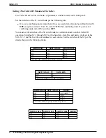
Pin 1 = No Connection
Pin 2 = (CTS) Clear to Send
Pin 3 = (RD) Receive Data
Pin 4 = (TD) Transmit Data
Pin 5 = (SG) Signal Ground
Pin 6 = No Connection
6
5
4
1
2 3
email004.cdr
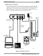
Versatitle Voice Processing
Voice Mail Computer
Typical
Rear View
Serial Data Ports
9-Pin and 25-Pin
Configurations
5
4
3
2
Front View
of Jack
6 5 4 3 2 1
RD
CTS
SG
For Serial Integration
Connect DSU II's
COM1 or COM2 Serial
Data Port To PC's
Serial Data Port
Typical
625A2
Modular
Jack
Industry Standard
Four-Conductor
Modular Line Cord
Typical modular to EIA adapter
wiring shown for reference only.
(Viewed from rear of PC)
14
15
16
17
18
19
20
21
22
23
24
25
1
2
3
4
5
6
Front
View of
Jack
SG
RD
TD
Connect to matching
serial data port on
voice mail computer
as appropriate
RTS
1
2
3
4
5
6
SG
RTS
RD
TD
9-DB to modular
25-DB to modular
4
6
4
6
8
9
8
9
10
11
Front
View of
Jack
TD
Voice
Board
Ports
Industry-Standard
Four-Conductor
Line Cord
Connect Voice Board Port To DSU II's
Industry-Standard Telephone Port
(Supplied By Either JM008 Expansion Module
Or ATI-D Analog Terminal Interface Device)
Connecting VVP To The Digital Telephone System
DSU II Digital Telephone System
IMI66–132
Installing The DSU II Digital Telephone System 2 – 87
Summary of Contents for DSU II
Page 31: ......


