


Reflect-O-Ray
®
Oil Fired EDS 3.5
Installation, Operation & Service
Combustion Research Corporation
Page 13
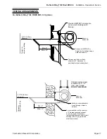
REFLECTOR INSTALLATION
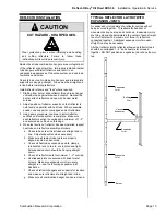
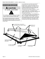
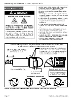
CAUTION
CUT HAZARD - SHARP EDGES.
Wear protective gloves when installing and handling
and cutting reflectors. Failure to follow these
instructions will result in personal injury.
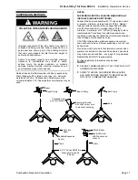
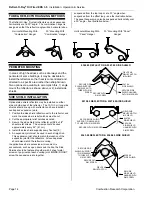
Radiant heat tube combination hangers are an integral part
of the reflector support system. Improperly installed radiant
tube hangers will distort reflectors and result in an
undesirable appearance of the entire system, and can lead
to vibration and noise.
Check to be sure all combination hangers and intermediate
supports are hanging straight. Tubes must be straight and
in line before installing reflectors.
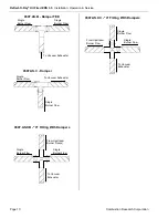
Install reflector elbows and "tees" where required.
1. Starting from burner slide reflector through tube hanger
until end stops against drawband coupler. Nearest the
burner, attach reflector end cap with 4 sheet metal
screws.
2. Adjust position of reflector supports so that reflector is
held level and parallel with heat tube. Where possible,
position one support at overlapped ends of reflectors.
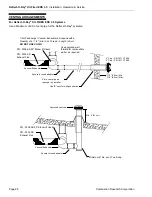
3. Using same procedure, continue to install reflector
sections until entire system is complete. Make sure
each reflector section is overlapped a minimum of 1 -2"
and secured as outlined on this page.
4. When last section of reflector has been installed, inspect
heat tube and reflector assembly as follows:
a. Check to be sure all heat tubes are straight and in
line. Adjust suspension when necessary.
b. Make sure all radiant tube joints are properly
aligned, sealed, and secured.
c. Check all heat tube suspension points, clamps,
turnbuckles, lock nuts, etc. are in place and tight.
All suspension chain should be hanging straight
down.
d. Check all reflector joints for minimum 1 - 2" overlap.
e. Overlapped joints are secured with sheet metal
screws. Make sure expansion joint is in every
straight run - see the following expansion joint
illustration.
f. Check all reflector hangers and supports for location
and make sure reflectors are straight and in line.
g. Make sure all combination hanger hooks are closed.
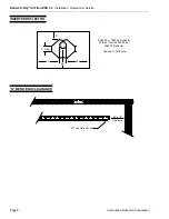
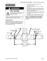
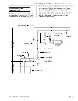
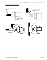
TYPICAL REFLECTOR LAYOUT WITH
EXPANSION JOINTS
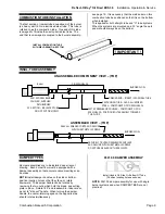
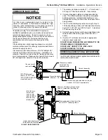
An expansion joint consists of a reflector overlap without
being secured together. This allows for freedom of
movement during heat up and cool down. Expansion joints
are to be placed at approximately the center of each straight
run of reflectors with a maximum of three (3) reflectors
connected together. Additional expansion joints in each
straight run may be necessary.
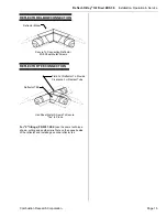
All other reflector joints, reflector elbows and reflector tee's
should be overlapped 1 - 2" and sheet metal screwed
together, DO NOT position an expansion joint at an elbow or
tee.
Burner
Building
Wall
Vacuum
Exhauster
Expansion
Joint
Expansion
Joint
Expansion
Joint
!