background image


59

TROUBLESHOOTING 


69.


THE MACHINE DOES NOT START 

1.


Check the batteries are charged (battery version) 

2.


Check the starter battery is charged (combustion engine version) 

3.


Check the starter battery is connected to the machine system (combustion engine version) 

4.


Check the electric system connector is connected to the battery connector (battery version) 

5.


Check the electric system connector is connected to the generator connector (combustion engine 
version) 

6.


Check the key switch is ON/I 

7.


Check there is fuel in the engine tank, and that the LPG cylinder is full (combustion engine version) 


70.


THE COMBUSTION ENGINE DOES NOT START 


WARNING: If the combustion engine does not start up, check the diagnostics 
in the motor use and maintenance manual (the booklet supplied with the 
machine itself). 


71.


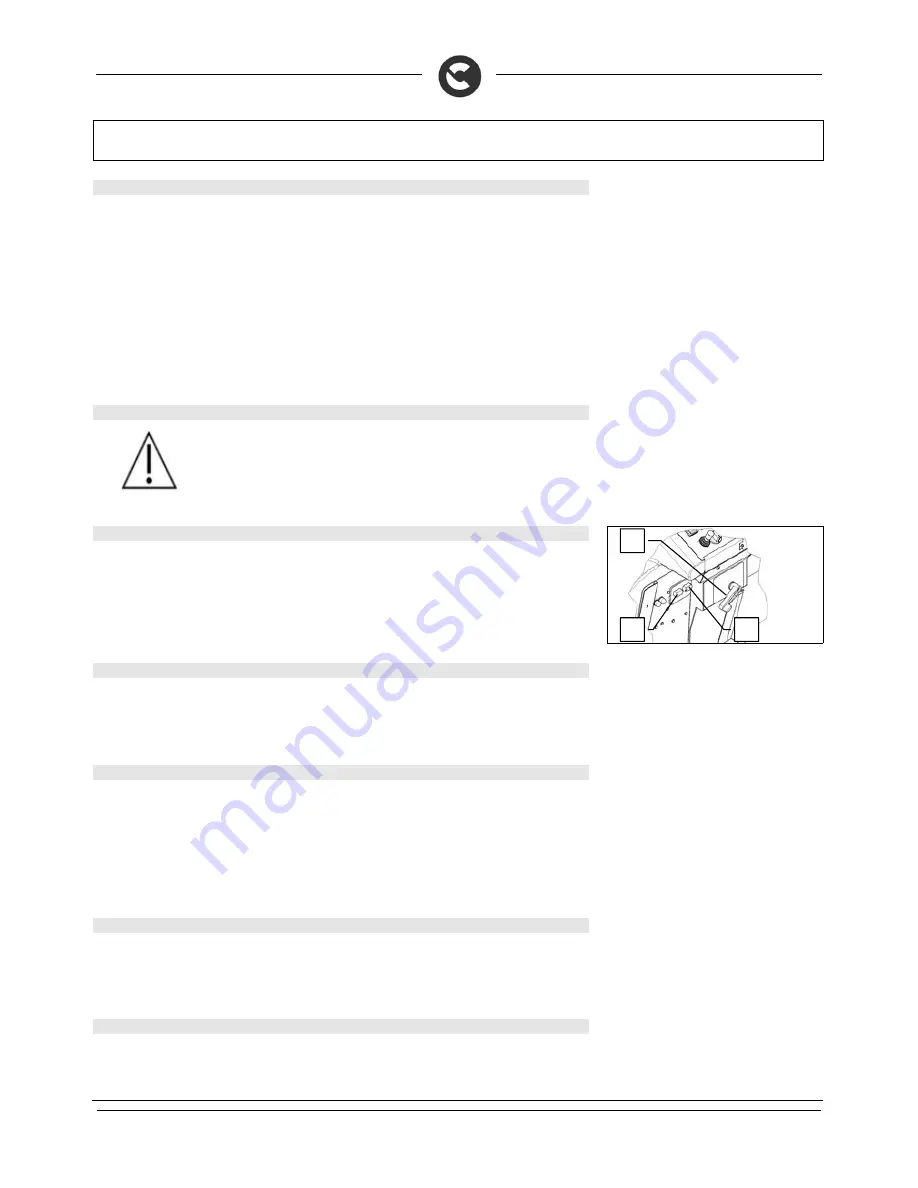
INSUFFICIENT WATER ON THE BRUSHES 

1.


Check there is water in the solution tank 

2.


Check that the water/detergent solution release adjustment lever (1) is open 

3.


Check that the water/detergent selectors (2-3) are open (for CDS versions only) 

4.


Clean the solution filter located at the front of the machine 

5.


Make sure the detergent solution distribution tank (on the brush head unit) is not clogged 


72.


THE SQUEEGEE DOES NOT DRY PERFECTLY 

1.


Check the squeegee is clean 

2.


Check the squeegee settings (see “MACHINE PREPARATION”) 

3.


Clean the entire vacuum unit (see “WEEKLY MAINTENANCE”) 

4.


Replace the rubbers, if worn 


73.


THE MACHINE DOES NOT CLEAN WELL 

1.


Check the state of wear and tear of the brushes and, if necessary, replace them. The brushes should 
be changed when the bristles are about 15mm long. To replace them, see “REPLACING THE 
BRUSHES”, or “DISASSEMBLING THE BRUSHES” and “ASSEMBLING THE BRUSHES”. Working 
with over-worn brushes may cause damage to the floor 

2.


Use a different kind of brush to the one fitted as standard. For cleaning floors where the dirt is 
particularly resistant, we recommend the use of special brushes supplied upon request and according 
to needs (see “CHOOSING AND USING THE BRUSHES”) 


74.


EXCESSIVE FOAM PRODUCTION 

Verify that a low foam detergent has been used. If necessary, add a small quantity of anti-foam liquid to the 
recovery tank. 
Remember that, when the floor is not very dirty, more foam is generated. In this case the detergent solution 
should be more diluted. 


75.


THE SUCTION MOTOR DOES NOT FUNCTION 

1.


Check whether the recovery tank is full and, if necessary, empty it 

2.


Check the float switch on the suction cap is working well (see also “CLEANING THE RECOVERY 
TANK” under “DAILY MAINTENANCE”) 


Summary of Contents for ULTRA100 BS

Page 1: ...USE AND MAINTENANCE MANUAL ULTRA100 BS ULTRA100 GS BI FUEL ED 02 2012 EN ORIGINAL INSTRUCTIONS Doc 10033331 Ver AA...

Page 2: ...ok symbol with an i Indicates the need to consult the instruction manual Open book symbol Used to tell the operator to read the manual before using the machine Warning symbol Carefully read the sectio...

Page 3: ...TERY CHARGER BATTERY VERSION 21 18 INDICATOR FOR BATTERY CHARGE LEVEL AND HOUR METER BATTERY VERSION 22 19 FILLING THE FUEL TANK COMBUSTION ENGINE VERSION 22 20 CONNECTING THE LPG CYLINDER COMBUSTION...

Page 4: ...BRUSHES 51 61 REPLACING THE SIDE BRUSH 52 62 REPLACING THE FRONT SQUEEGEE RUBBER 53 63 REPLACING THE REAR SQUEEGEE RUBBER 54 64 REPLACING THE SIDE SPLASH GUARD RUBBER OF THE BRUSH HEAD 54 65 REPLACIN...

Page 5: ...oklet carefully and read it again whenever difficulties arise while using the machine If necessary remember that our customer assistance service organised in collaboration with our dealers is always a...

Page 6: ...r No V W 2 36 670 2 36 670 Suction vacuum mbar 190 190 Rear elastic wheels diameter width mm 370 x 140 370 x 140 Solution tank l 280 280 Recovery tank l 285 285 Detergent tank CDS version only l 15 St...

Page 7: ...e direction of the machine Symbol denoting acoustic alarm Indicates the acoustic alarm button Symbol denoting forwards and backwards speed selector Used on the instrument panel to indicate the speed o...

Page 8: ...ution in the solution tank Symbol denoting full recovery tank Used on the instrument panel to indicate the red warning light showing that the dirty water level has reached a critical level Symbol indi...

Page 9: ...d on the front right hand panel to indicate the green warning light showing that the main key switch is ON Symbol for the combustion engine rpm potentiometer only on versions with internal combustion...

Page 10: ...ulation Used on the central panel of the steering cover to indicate the tap lever to regulate the water Label warning operator to take safety measures to avoid damage to limbs Label indicating the pos...

Page 11: ...n Indicator showing battery charge level on the upper line and hour meter on the lower line Indicator showing the type of hour meter total on the upper line and the type of service none on the lower l...

Page 12: ...ter and detergent quantity CDS system only Used on the left hand panel to indicate the knobs for adjusting the percentage level of detergent dissolved in the water and the level of water distributed o...

Page 13: ...owders Do not mix different types of detergent as this may produce harmful gases The machine is not suitable for cleaning carpets Do not place any liquid containers on the machine Avoid working with t...

Page 14: ...assemble the squeegee read the ASSEMBLING THE SQUEEGEE paragraph 5 Keep the pallet for any future transport needs WARNING If the product is delivered in cardboard containers handle the packed product...

Page 15: ...ee D Washing only use brushes only 10 Red warning light indicating that the motor brush head is working under pressure force 11 Red warning light indicating that there is a malfunction in the machine...

Page 16: ...mal position 21 Green warning light indicating that the squeegee unit has reached its operating position 22 Green warning light indicating that the left hand suction motor is in operation 23 Green war...

Page 17: ...ngine 32 2 way switch for selecting the type of fuel to be injected into the combustion engine carburettor on versions with combustion engine 5 FOOTBOARD COMPONENTS The components at the front right o...

Page 18: ...are identified as follows 40 Suction cover release hinge 41 Recovery tank release hinge 8 MACHINE S REAR COMPONENTS The rear components of the machine are identified as follows 42 Recovery tank discha...

Page 19: ...tandards CEI EN 50342 CEI EN 60095 2 and CEI EN 60095 4 12 BATTERY MAINTENANCE AND DISPOSAL For maintenance and recharging comply with the instructions provided by the battery manufacturer Particular...

Page 20: ...ight and method of lifting They must also satisfy the requirements of Standard CEI 21 5 The dimensions of the battery compartment are 879 mm x 599 mm x H450 mm WARNING For battery maintenance and dail...

Page 21: ...nect the battery connector cable to the machine connector WARNING You are advised to have the electric connections made by a qualified COMAC trained technician WARNING You are advised to always wear p...

Page 22: ...exhalation and leakage of corrosive liquids WARNING Danger of fire do not go near with free flames 18 INDICATOR FOR BATTERY CHARGE LEVEL AND HOUR METER BATTERY VERSION On the instrument panel of the m...

Page 23: ...soline is stored WARNING During the filling operation be careful not to spill the fuel Spilt fuel or fuel vapours could ignite If any fuel is accidentally spilt remove it thoroughly before switching o...

Page 24: ...each this speed the eight indicators will appear on the display 22 TURNING LIGHTS ON OFF The machine is equipped with two headlights and a rear spotlight to help the operator to work in low light To s...

Page 25: ...WARNING The reverse speed is lower than the forward speed to comply with current health and safety standards 25 MOVEMENT OF THE SIDE BRUSH This machine is able to increase the working width by exploit...

Page 26: ...formation of excess foam could damage the suction motors so only use the minimum amount of detergent needed WARNING Always use detergents suitable for scrubbing machines as indicated on their label Do...

Page 27: ...machine in the traditional way by adding the detergent in the clean water tank and excluding the dosing circuit WARNING Always use detergents suitable for scrubbing machines as indicated on their labe...

Page 28: ...lower value is equal to 0 5 for standard detergents or 0 1 for a concentrated detergent diluted as indicated on the label supplied with the machine while the higher value is equal to 3 5 or 0 7 with 7...

Page 29: ...r is slightly tilted backwards by about 5mm in a uniform way for its whole length If you need to increase the bend of the rubber in the central part you must tilt the squeegee unit To do this proceed...

Page 30: ...ight hand splash guard pre assembly 2 loosening the screws 3 that fix it to the brush head 6 Remove the nuts 4 from the right hand carter 7 Remove the screw 5 from the right hand carter 8 Remove the n...

Page 31: ...nel WARNING Make sure the brushes are correctly connected If they are not the machine may not work properly WARNING You are advised to always wear protective gloves to avoid the risk of serious injury...

Page 32: ...product WARNING Always use low foam detergent To avoid the production of foam before starting to clean put a minimum quantity of anti foam liquid into the recovery tank Do not use pure acids 7 Refit t...

Page 33: ...l hour counter to display a different type for instance partial contact the qualified COMAC trained personnel The bottom line shows the service setting in this case there is no setting 8 The second sc...

Page 34: ...rn to position 1 Bring the motor ignition switch to the START position turning the key further to the right and keep it there until the motor starts up you can now release the key WARNING Do not use t...

Page 35: ...m flow of water This lever should not be used to make adjustments To ensure the correct dose on the brushes use only the knobs for adjusting the amount of water solution 5 and detergent 6 See paragrap...

Page 36: ...NE 3 Turn the main switch key 1 clockwise by a quarter of a turn to position 1 Bring the motor ignition switch to the START position turning the key further to the right and keep it there until the mo...

Page 37: ...rument panel comes on while you are working this means the brake oil level is low down to reserve Top up the level as soon as possible 41 MOVEMENT OF THE SIDE BRUSH This machine is able to increase th...

Page 38: ...r connector for versions with a combustion engine WARNING Before carrying out any type of maintenance remove the keys from the panel and disconnect the battery connector for battery versions or from t...

Page 39: ...on the machine 18 Disengage the parking brake 19 Park the machine in a closed place in an area where it cannot cause damage to people or other property but also be protected from an accidental fall o...

Page 40: ...r from the generator connector for versions with a combustion engine 45 CLEANING THE SQUEEGEE Careful cleaning of the whole suction group ensures better drying and cleaning of the floor as well as gre...

Page 41: ...er cap 1 5 Disconnect the clean water drain hose 2 from its housing at the rear of the machine unscrew the cap and empty the tank 6 Close the water tap 3 7 Unscrew the filter 4 at the front of the mac...

Page 42: ...dangerous solutions 6 Rinse the inside of the hopper with a jet of clean water 7 Take the suction filter 4 out of the debris hopper and clean it under a jet of running water 8 Reassemble the suction...

Page 43: ...upper limit notch To do this use the tube 4 Do not over fill WARNING Check the oil level when the motor is switched off and with the machine on an even surface WARNING Refer to the motor use and main...

Page 44: ...nel and disconnect the battery connector for battery versions or from the generator connector for versions with a combustion engine WARNING This operation must be carried out using gloves to protect a...

Page 45: ...gage it by means of the lever 1 4 Ensure the solution tank is empty otherwise empty it 5 Close the water tap 2 6 Disconnect the solution tank drain hose 3 located at the rear of the machine 7 Unscrew...

Page 46: ...ct with dangerous solutions 55 CLEANING THE SOLUTION TANK FILTER Proceed as follows for cleaning 1 Check the electric system connector is disconnected from the battery connector for battery versions o...

Page 47: ...ombustion engine 3 Make sure the main switch is in the 0 position If it is not turn the key a quarter turn to the left 4 Check the parking brake is engaged If it is not engage it by means of the lever...

Page 48: ...elease the brush from the brush holder plate seat and turn it anticlockwise until the three studs slip out of the notches on the plate itself Turn so the stud is pushed away from the coupling spring 6...

Page 49: ...e the brush head unit is in its working position if necessary turn the I DRIVE selector to the Washing position to lower the brush head 2 Check the electric system connector is disconnected from the b...

Page 50: ...ed to the distribution basin cover 8 Push the distribution basin towards the left side of the machine then lift it and remove it from the brush head unit 9 Remove the cover 6 from the detergent soluti...

Page 51: ...disconnected from the battery connector for battery versions or from the generator connector for versions with a combustion engine 3 Make sure the main switch is in the 0 position If it is not turn th...

Page 52: ...ine may not work properly WARNING You are advised to always wear protective gloves to avoid the risk of serious injury to your hands 61 REPLACING THE SIDE BRUSH If the side brush is worn it will no lo...

Page 53: ...nd the machine will not dry perfectly if the front squeegee rubber is worn Proceed as follows to replace 1 Make sure the brush head unit is in its working position if necessary turn the I DRIVE select...

Page 54: ...rubber to turn it over or replace it 8 To replace the rubber proceed in reverse order 9 Adjust the height of the squeegee depending on the rubber see ADJUSTING THE HEIGHT OF THE SQUEEGEE SUPPORT WARNI...

Page 55: ...f the relevant lever on the instrument panel 3 Set the main switch to the 0 position by turning the key a quarter turn to the left 4 Check the electric system connector is disconnected from the batter...

Page 56: ...he old cylinder and the new one are closed WARNING The cylinder and tube 4 must never be exposed to heat sources 67 REPLACING THE STARTER BATTERY The battery must be housed in the special compartment...

Page 57: ...le 12 Fix the battery to its support with the aid of the clamp 3 68 WASHING THE DOSING SYSTEM VERSIONS WITH CDS The dosing system should be cleaned when the machine is not used for a long period more...

Page 58: ...percentage adjustment knob 4 to the maximum position 12 Insert the battery connector into the machine connector 13 Place the main switch in position ON I 14 Disengage the parking brake 15 Make sure th...

Page 59: ...e brush head unit is not clogged 72 THE SQUEEGEE DOES NOT DRY PERFECTLY 1 Check the squeegee is clean 2 Check the squeegee settings see MACHINE PREPARATION 3 Clean the entire vacuum unit see WEEKLY MA...

Page 60: ...ess the specific circuit breaker button to reactivate the power supply and motor operation If the problem persists contact the technical assistance centre 78 THE AUTOMATIC WATER DETERGENT DOSING SYSTE...

Page 61: ...parate the following materials and send them to the appropriate collection centres in accordance with the environmental hygiene regulations currently in force brushes filter electric and electronic pa...

Page 62: ...id and are no longer able to penetrate and clean deep down In this case like with over large bristles the brush tends to jump PAD HOLDER The pad holder is recommended for cleaning shiny surfaces There...

Page 63: ...odology EN 12100 2 Machine safety Fundamental concepts fundamental principles of design Part 2 Technical principles EN 61000 6 2 Electromagnetic compatibility EMC Part 6 2 Generic standards Immunity f...

Page 64: ...odology EN 12100 2 Machine safety Fundamental concepts fundamental principles of design Part 2 Technical principles EN 61000 6 2 Electromagnetic compatibility EMC Part 6 2 Generic standards Immunity f...

Reviews: