background image


SC Scanner Instruction Manual


Page 14 of 23 

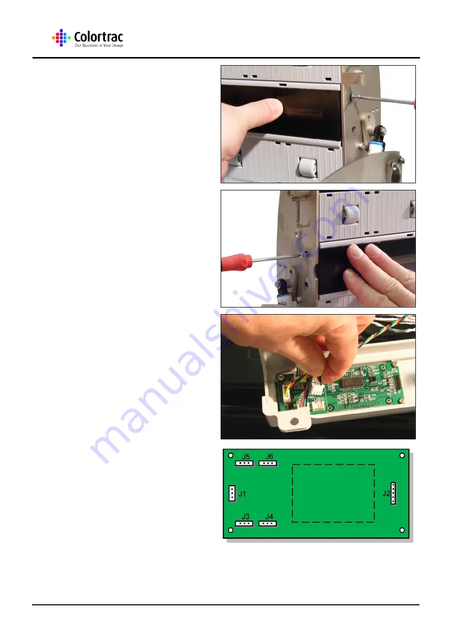
33.  While holding the 

SingleSensor CIS Assy flat in 
place, refit the 2 x M3 screws 
into the right end, but do not 
tighten at this stage. 


34.  Refit the 2 x M3 screws into 

the left end, but do not 
tighten at this stage. 


35.  Before fully tightening the 4 x 

M3 screws, apply slight 
pressure on the SingleSensor 
CIS Assy to hold in place, 
and then tighten the screws. 


36.  Reconnect the 4 x Paper 

Sensor Cables, making sure 
the correct cable is in its 
referenced socket. 
Reconnect the Control Cable 
from the Main board into J1. 


37.  Make sure all the cables are 

in their correct location on the 
Control Board. 


Summary of Contents for SingleSensor CIS

Page 1: ...This is a confidential controlled document and is the property of Colortrac Ltd It is not to be copied or reproduced in part or whole C Co ol lo or rt tr ra ac c S SC C S Sc ca an nn ne er r S Si in n...

Page 2: ...Misprints errors or quality observations should be reported to Technical Support Colortrac Ltd Colortrac Ltd shall not be liable for any damages errors issues or events that result from the use of th...

Page 3: ...SC Scanner Instruction Manual Page 3 of 23 CONTENTS 1 Tools Required 4 2 Photos Information 4 3 SingleSensor CIS Assy 5 4 Calibration 20 5 Auto stitch 22...

Page 4: ...length 6 Small Pozi drive screwdriver PZ0 x 60mm length 7 Small Flat Screwdriver 3mm blade x 65mm length approx 8 Medium Flat Screwdriver 6mm blade approx 9 Pliers Flat nosed pliers short serrated 2...

Page 5: ...her end of the Lid Assembly 2 Allow the Lid Assembly to gently open 3 Carefully remove the 2 x M4 screws holding the left end of the Top Lid Cover Take care not to drop the screws while removing them...

Page 6: ...Assembly making sure both Lid Latches lock securely 6 Carefully lift the Top Lid Cover off from the Lid Assembly 7 Remove the Aluminium EMC Tape covering the cables to the Main Board 8 Remove the 4 x...

Page 7: ...e Suppressor leads on the Main Board cover as they can be broken with repeated or excessive movement 10 Remove the Main Board Cover and store in a safe place 11 The Main Board cover for the SC25 is di...

Page 8: ...C Scanner Instruction Manual Page 8 of 23 13 Gently pull the ribbon cable from the connector 14 Disconnect the 4 x LED cables J10 13 15 Remove the M3 x 4 screws holding the Control Board Bracket Cover...

Page 9: ...ge 9 of 23 16 Remove the Control Board Bracket Cover 17 Before removing the Control Board Bracket Assembly use a pencil to mark its position 18 Remove the 4 x M3 screws holding the Control Board Brack...

Page 10: ...emove the Control Board Bracket and store safely until refitting 21 To raise the lid into the maintenance position remove the 3 x M5 screws holding the left end Gas Piston Bracket to the Lid Assembly...

Page 11: ...e lift the Lid to the 90deg position 24 Tighten the locking screws in the Hinge Bracket at the left end of the Lid Assembly The Lid may need to be moved slightly to allow the screws access 25 Tighten...

Page 12: ...the 2 x M3 screws from the right end of the SingleSensor CIS Assy NOTE With your free hand hold the SingleSensor CIS Assy in place to prevent it dropping and being damaged 28 Gently remove the Single...

Page 13: ...ly 31 Feed the LED cables from the new SingleSensor CIS Assy through the Lid Assembly before lifting it into place continuing to pull the cables through the Lid Assembly as the SingleSensor CIS Assy i...

Page 14: ...ft end but do not tighten at this stage 35 Before fully tightening the 4 x M3 screws apply slight pressure on the SingleSensor CIS Assy to hold in place and then tighten the screws 36 Reconnect the 4...

Page 15: ...ews to hold the Control Board Bracket Assembly to the Lid Assembly 39 Fit the Control Board Bracket Cover and make sure all the cables are in the cut out 40 Refit the 4 x M3 screws to hold the Control...

Page 16: ...he CIS Ribbon cable is fully in place secure it by pressing down both sides of the locking plate 43 Reconnect the 4 x LED cables J10 13 ensuring the correct cable is inserted in the correct plug 44 Ma...

Page 17: ...place 46 After making sure all the cables are in their appropriate cutout and the USB connector is also in it s cutout in the cover fit 4 x M3 screws to hold the Main Board Cover in place 47 Refit the...

Page 18: ...h the 3 x M4 screws of the Right Gas Piston Make sure not to drop the screws into the scanner 50 Similarly reattach the Left Gas Piston with the 3 x M4 screws Make sure not to drop the screws into the...

Page 19: ...nnect the Power and USB cables to the Scanner and power up the scanner and Utilities Program 53 Run the Calibration as described in chapter 4 Calibration page 20 54 Run the Auto stitch as described in...

Page 20: ...ert the Calibration Target so that the black part section is inserted first face up NOTE It is necessary to remove the Magnetic Paper Guide AND the Document Return Guide if it is fitted to the scanner...

Page 21: ...ruction Manual Page 21 of 23 5 Click OK to except the message 6 After approx 4 minutes the Calibration or Normalisation is complete During calibration the target will move through the scanner in stage...

Page 22: ...of the front page 2 Insert the Calibration Target so that the black section is in first and face up NOTE It is necessary to remove the Magnetic Paper Guide AND the Document Return Guide if it is fitt...

Page 23: ...SC Scanner Instruction Manual Page 23 of 23 4 Click OK to except the message 5 On completion click the OK button Useful Information FB stitch range 0 32 LR stitch range 0 88...

Reviews: