background image


SC Scanners Main Board


Page 21 of 21 


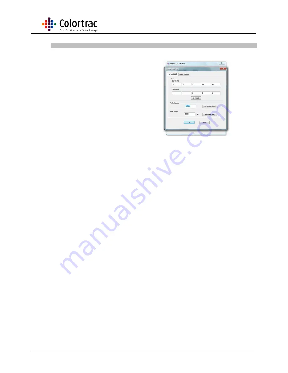
Motor Speed 


1.  On the Main Page, right 

click and enter the 
Distributors Utilities. Enter 
the password ‘p107’. 


2.  When changing a Main 

Board, this values might 
need to be recorded prior to 
removing the board if the 
reference lable is damaged 
or missing from under the 
scanner. Record this value. 


3.  After fitting a Main Board, 

over write the value at this 
point with the recorded 
value, and click ‘Set Motor 
Speed’ 


Summary of Contents for SC Main Board

Page 1: ...l Date 12 02 14 This is a confidential controlled document and is the property of Colortrac Ltd It is not to be copied or reproduced in part or whole It is intended for staff to read C Co ol lo or rt...

Page 2: ...or Misprints errors or quality observations should be reported to Technical Support Colortrac Ltd Colortrac Ltd shall not be liable for any damages errors issues or events that result from the use of...

Page 3: ...SC Scanners Main Board Page 3 of 21 CONTENTS 1 Tools Required 4 2 Photos Information 5 3 Top Lid Cover 5 4 Main Board 7 5 Calibration 15 6 Firmware Installation 17 7 Auto stitch 19 8 Motor Speed 21...

Page 4: ...Colortrac to supply 1 Wristband Anti static and cable 2 Pencil HB Lead 3 7mm Nutdriver To remove and fit M5 nuts 4 1 5mm Allen Key or 1 5mm Hex Key 5 Medium Pozi drive screwdriver PZ1 x 80mm length 6...

Page 5: ...me background panels may be shown in the photo to be removed when they actually don t need to be however the instructions are still correct and should be followed as described 3 Top Lid Cover 1 To rem...

Page 6: ...Close the Lid Assembly making sure both Lid Latches lock securely 6 Carefully lift the Top Lid Cover off from the Lid Assembly 7 Replace the Top Lid Cover in the reverse order making sure the Control...

Page 7: ...n page 21 1 Remove the Aluminium EMC Tape covering the cables to the Main Board 2 Remove the 4 x M3 screws holding the Main Board Cover to the Lid Assembly 3 WARNING Gently lift the Main Board Cover t...

Page 8: ...5 The Main Board cover for the SC25 is different than for the SC36 24 but should be removed in the same way as shown here 6 Gently lift the locking bar on each ribbon cable connector Don t use too mu...

Page 9: ...SC Scanners Main Board Page 9 of 21 8 Disconnect the Microswitch cable 9 Disconnect the Mains Cable Motor Control Cable and the 4 x LED Control Cables 10 Disconnect the Control Board Cable...

Page 10: ...he 6 x M3 screws holding the Main Board to the Lid Assembly 12 Remove the Main Board using anti static precautions 13 To refit the Main Board position onto the 6 spacers making sure no cables are trap...

Page 11: ...11 of 21 15 Reconnect the Microswitch cable 16 Reconnect the Control Board Cable at J9 as well as the Motor Control Cable 17 Re insert the CIS Ribbon cables into J1 J3 making sure the locking plate i...

Page 12: ...he CIS Ribbon cable is fully in place secure it by pressing down both sides of the locking plate 19 Reconnect the 4 x LED cables ensuring the correct cable is inserted in the correct plug 20 Make sure...

Page 13: ...ce 22 After making sure all the cables are in their appropriate cutout and the USB connector is also in it s cutout in the cover fit 4 x M3 screws to hold the Main Board Cover in place 23 Refit the Al...

Page 14: ...s not for the SC scanner and should be ignored 26 Reconnect the Power and USB cables to the Scanner and power up the scanner and Utilities Program on a PC 27 Set the Motor Speed as described in chapte...

Page 15: ...lose the Lid Assembley 2 Insert the Calibration Target so that the black part section is inserted first face up NOTE It is necessary to remove the Magnetic Paper Guide so the target can fit centrally...

Page 16: ...Main Board Page 16 of 21 5 Click OK to except the message 6 After approx 4 minutes the Calibration or Normalisation is complete During calibration the target will move through the scanner in stages se...

Page 17: ...firmware cab file click download 3 Agree to the warning message NOTE It is important to allow the firmware to complete Although the Main Board now carries a backup firmware there is still a possibili...

Page 18: ...SC Scanners Main Board Page 18 of 21 4 Once the download has finished it will request the scanner and software are both Re cycled...

Page 19: ...t the Calibration Target so that the black section is in first and face up NOTE It is necessary to remove the Magnetic Paper Guide so the target can fit centrally in the scanner 2 Click Auto stitch bu...

Page 20: ...SC Scanners Main Board Page 20 of 21 4 On completion click the OK button Useful Information FB stitch range 0 32 LR stitch range 0 88...

Page 21: ...Enter the password p107 2 When changing a Main Board this values might need to be recorded prior to removing the board if the reference lable is damaged or missing from under the scanner Record this v...

Reviews: