background image


                                                                                                                                                                            Page 

12

 of 

40


SoniQ i


The 

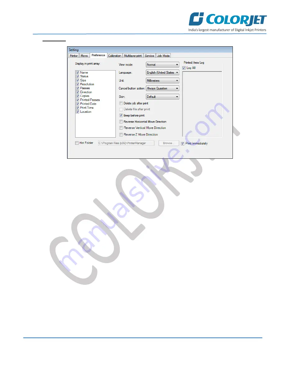
Preference

 tab is shown in the image below: 


Fig 10: Displaying the Preference Tab 

Description of different options available under the Preference tab: 


View Mode

: Enable to set the Printer Manager screen view.  


Language: 

Enable to change the language of the Printer Manager.  


Unit: 

Enable to set the measuring unit like Millimeter. 


Summary of Contents for SONIQ i

Page 1: ......

Page 2: ...thout anyone else assistance The information provided in this document ensures its uniqueness and language quality For safe and proper use of the product please read this manual carefully and follow a...

Page 3: ...etting Menu 9 Tools Menu 13 Help Menu 14 6 Getting Ready for Printing 15 Switch ON Procedure 15 Loading Media 16 Ink Refilling 18 Feeding Password 19 7 Printing 20 Nozzle Testing 20 Print Head Calibra...

Page 4: ...urging 33 Head Spraying 34 9 Shutdown Capping the Print Head 35 10 Maintenance 36 Print Head Maintenance 36 Equipment Cleaning 36 Power System Maintenance 36 Control System Maintenance 36 Ink Supply S...

Page 5: ...ocument is designed to facilitate both types of users 2 Machine Specifications Machine Specifications are shown in the table below SoniQ i SNQ 4412 Printing Technology Drop on demand Piezo Electric In...

Page 6: ...is shown as below Fig 1 Displaying the Front View Table 1 Different Parts of SoniQ i 1 Carriage Unit Location 2 Front Cover 3 Console TFT Screen 4 Emergency Switch 5 Control Panel Unit 6 Leveler 7 Dry...

Page 7: ...SoniQ i Back View The Back View of the machine is shown as below Fig 2 Displaying the Back View Table 2 Different Parts of the Machine 1 Media Lever 2 Supply Roller 3 Power Inlet Machine and Heater Sw...

Page 8: ...ine is given as below HEAD Power Turn ON OFF the print head power HEATER Turn ON OFF the pre and post heaters MEDIA TAKE UP Enable to turn ON OFF control different modes auto manual and change directi...

Page 9: ...elete Job Print Job Pause or resume Abort job check nozzle Auto clean Move left Move right Set print origin Move forward Move backward Move carriage to origin and Edit job are available as buttons on...

Page 10: ...reated for further references Load Using this option you can load the previously saved machine s settings Save To Printer When you click on this option all the current settings get saved in the Main B...

Page 11: ...the feed motor during printing o Job Space Set space between multiple jobs o Feather Feather type should be Gradient only and intensity percentage of the feather should be 5 100 as per the media type...

Page 12: ...increased spray frequency gets decreased o Print Pre spray Time This is the duration of spray before start of print This option works when the Spray Before Print option is enabled o Idle Spray Spray d...

Page 13: ...10 Displaying the Preference Tab Description of different options available under the Preference tab View Mode Enable to set the Printer Manager screen view Language Enable to change the language of t...

Page 14: ...w Fig 12 The Tools Menu Option Describing the different options of the Tool Menu Password This option enables to feed the time and language passwords of the printer Calibration Wizard Using this optio...

Page 15: ...when time out occurs with a pop up message as shown below Fig 13 Displaying the Error Message Help Menu The Help menu option is shown in the image below Fig 14 The Help Menu Option About Enable to vi...

Page 16: ...N the print engine and heater power buttons as shown below Fig 15 Switch ON the Print Engine and Heater Power Step 8 Load the media refer to the Media Loading section Step 9 Turn on the computer syste...

Page 17: ...nwind the media roll to reach near the platen and hold it Step 3 Insert the taken out media between the platform and the pinch roller Step 4 Pull the media out in front of the machine Step 5 Holding t...

Page 18: ...Up roller Optional or let the media down by issuing the Print command Step 9 Paste the front edge of the media on the core Step 10 Turn on the Take Up System and observe the media direction either re...

Page 19: ...ed ink in the printer for high printing quality as well as long life of print and print heads To refill ink open the left door of the printer and replace ink bottles if empty Ink gets filled in the Su...

Page 20: ...hown below Fig 21 Selecting the Password Option The Password window appears on the screen as shown below Fig 22 The Password Window Step 2 Feed Password in the Time Password field Refer to Fig 22 Note...

Page 21: ...elow Fig 23 Good and Bad Nozzle Test Result To check the nozzle click on the Check Nozzle icon available on the Quick Access Toolbar as shown below Fig 24 Clicking the Check Nozzle Icon In case of blo...

Page 22: ...sure good printing quality To open the Calibration Wizard click on the Main Menu Tools Calibration Wizard path as shown below Fig 25 Selecting the Calibration Wizard Option This should bring up the ca...

Page 23: ...racy and quality Bi direction Calibration Bi directional calibration is performed to achieve dot placement accuracy between the Left to Right and Right to Left print sweeps If the bi direction offset...

Page 24: ...the default set value It has to be performed for each print mode whichever is required Left to Right and Right to Left Calibrations Left to Right Calibration is performed to achieve dot placement acc...

Page 25: ...the printer moves the media forward for the next pass This movement of media is called a step The distance by which the media is moved is called the step size and it has to be accurate Step size error...

Page 26: ...that the pattern is corrected at 0 position The Step Calibration and its parameters are shown in the image below Fig 31 The Step Calibration Parameters Note Base Step value should be 51200 Follow the...

Page 27: ...Toolbar as shown below Fig 33 Selecting the Set Print Origin Option On clicking the Set print origin icon the current position of the carriage gets updated in the Origin X text box as shown below Fig...

Page 28: ...Standard Speed and Low Adding Jobs There are two ways to add jobs in the Job List area viz the Add Job button and right click on the Job List area Follow these steps to add jobs in the Job List area...

Page 29: ...eir Details Once a file has been added its information such as file path size resolution and number of passes can be viewed in the Job Information area User can also add a job simply by right clicking...

Page 30: ...t the job for which details you want to edit from the Job List area and right click Step 2 Select on the Edit option from the context menu as shown below Fig 40 Selecting the Edit Job Option Step 3 Se...

Page 31: ...efer to Fig 41 Ripping and Printing Ripping is an independent process which converts a raw image file into the machine readable format and get the file ready for printing The Rip software supports the...

Page 32: ...find any defect during the printing process you can immediately pause or cancel the current printing job using the Pause or resume and Abort Job buttons available on the Quick Access Toolbar as shown...

Page 33: ...needs to bend down to position it properly Don t move the wiper on the sides of nozzle plate it may attract the dried ink residues along with dust Don t pull out the wiper blade out of head plate area...

Page 34: ...nozzles If printer is in idle for more than 10 mins please perform the purging process In the printer The Head Purging button for each color is available on the carriage as shown in the below figure...

Page 35: ...y also clear few dry nozzles When heads are sprayed all the nozzles are actuated at a high rate which helps in opening up few dry nozzles of the printer To perform head spraying click on the Spray but...

Page 36: ...Step 4 Wet the tissue with the head cleaning solvent Step 5 Put the wet tissue on the Night Plate The Night Plate has four magnetic points on the corners of it The Night Plate with wet tissue is shown...

Page 37: ...ronment Prevent the object or human body with static contact to the print head Print head nozzles should be kept clean dust free and also prevent from oxidation Equipment Cleaning Turn OFF all power s...

Page 38: ...transfer Ground wire is disconnected Encoder scale is having ink stains Pulley or belt is slipping Ripped file is having error PRINT MARGIN IS SHIFTING OR JUNK PRINTING Encoder scale is having ink sta...

Page 39: ...nd verify by performing nozzle testing Check if any air lock or no ink in the ink pipes Check the ink and air pipe for any cuts or loose connection TAKE UP NOT WORKING Take up switch is not ON or not...

Page 40: ......

Page 41: ...For Any Query Please Contact Us www colorjetgroup com Call us on 91 120 4548195 Email on info colorjetgroup com For Ink Enquiry sales colorjetgroup com For Support support colorjetgroup com...

Reviews: