38
6 SYSTEM CONSTRUCTION
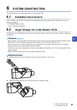
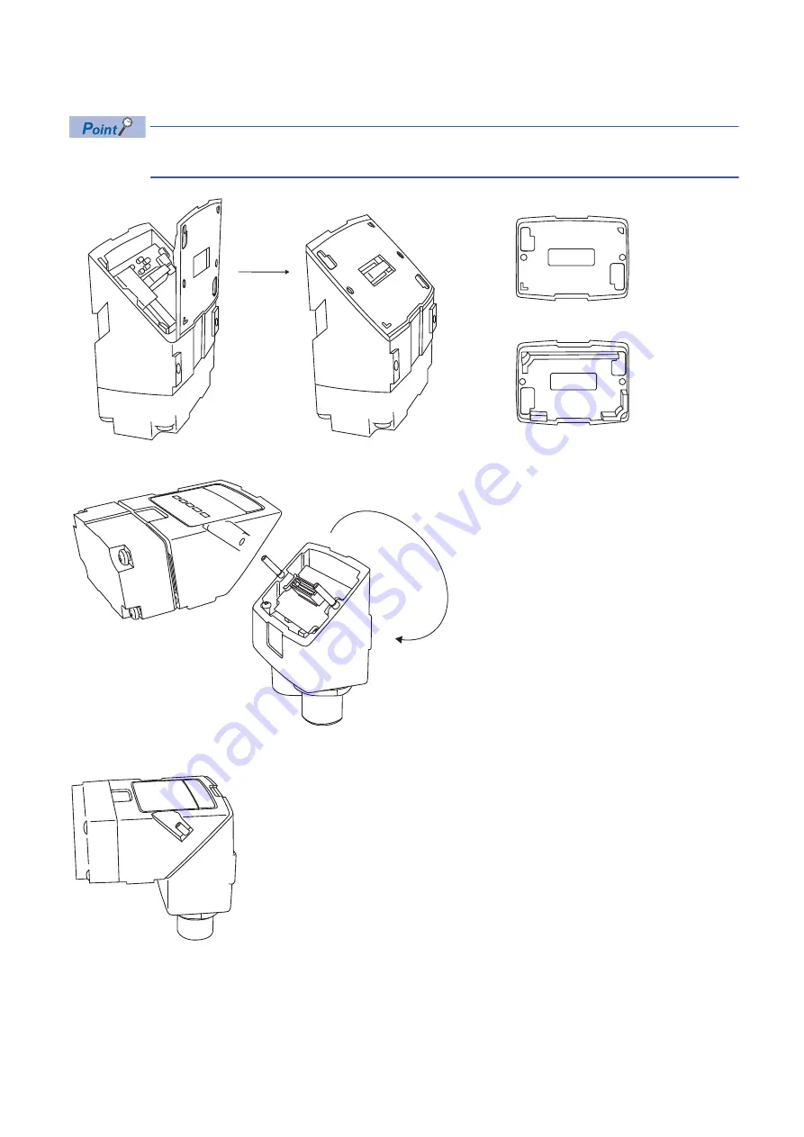
6.2 Angle Change of a Code Reader CF26
3.
Align the lower edge of a gasket onto the bottom surface of the main module, and then compress the upper edge of the
gasket to fix the module.
The surface of the gasket as shown below is the side where the I/O connector module is attached.
Make sure that the gasket is properly fixed on the main module.
4.
Change the orientation.
5.
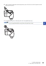
Reattach the I/O connector module to the main module.
The surface of a gasket
The rear of a gasket
Bottom
Bottom
Summary of Contents for Mitsubishi Electric MELSENSOR CF26 Series
Page 2: ......
Page 14: ...12 1 PRODUCT OVERVIEW MEMO...
Page 30: ...28 4 FUNCTIONS 4 1 Function List MEMO...
Page 49: ...7 INSTALLATION 7 2 Registration of a Profile 47 7 MEMO...
Page 51: ...8 MAINTENANCE AND INSPECTION 8 3 Cleaning a Lens Cover 49 8 MEMO...
Page 53: ...9 TROUBLESHOOTING 9 1 Error Checking Method 51 9 MEMO...
Page 58: ...56 APPX Appendix 2 External Dimensions MEMO...
Page 59: ...APPX Appendix 2 External Dimensions 57 A MEMO...
Page 63: ......

