3
Cognex CDC Series Camera Description
Cognex MVS-8100D and CDC Cameras Hardware Manual
57
Cognex software provides methods for enabling the strobe feature, for setting the
strobe’s pulse duration and pulse delay, and for setting the software to match the strobe
device’s polarity.
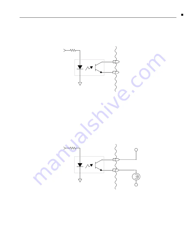
The schematic of the strobe output circuit is shown in Figure 30.
Figure 30. Strobe output schematic
Strobe Wiring Options
You can wire the optically isolated outputs in one of two ways:
voltage source output
wiring
or
contact closure output wiring
.
Figure 31 shows an example of the voltage source output wiring configuration. You
connect an external power supply (for example, 24 VDC) to . Connect Strobe–
to the strobe device. The strobe device should present enough impedance so that no
more than 125 mA flows through the circuit.
Figure 31. Source output wiring of strobe
Opto-isolator
Strobe –
330
Ω
Camera
Output
Strobe
Opto-isolator
Strobe –
330
Ω
Camera
Output
Strobe
+ V
Strobe
+ V return


