28
D026227_08 CR822x Single Board Decoded Scan Engine Integration Guide
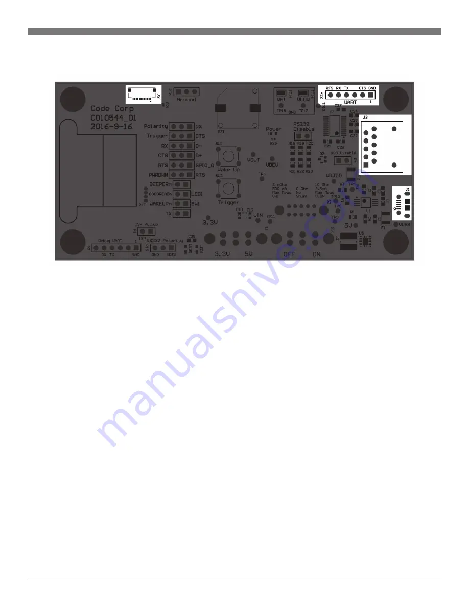
J3 is the standard Code RJ50 interface which supports RS232 using the
CRA-C501 cable and USB using the CRA-C500 cable. The connector also
provides a trigger signal to activate the engine remotely.
J1 provides a micro-USB interface for the CR8221 and CR8211. If both
the RJ50 and micro-USB cables are attached, micro-USB will be used for
communication. However, if power is connected to the RJ50 cable, the
development board will select it as the power source over micro-USB.
P12 provides a header to connect an FTDI cable for RS232
communication on the CR8222 and CR8212. When using this
communication method, a jumper must be placed on the “RS232
Disable” header in order to turn off the MAX3223 transceiver. The
system can be powered from either J3 or J1.
J2 is a 12 pin 0.5mm pitch ribbon connector that is used to connect the
engine. A reversed cable must be used such as 687712100002 made by
Wurth Electronics.
9.1 – Interface


