6
2. THIRTEEN PIN HARNESS, CONTINUED
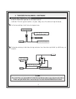
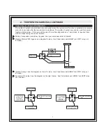
Wait-To-Start Input (+) (GRAY/BLACK)
Locate the Wait-To-Start light wire at the instrument panel.
Verification: This wire registers positive or negative voltage when the wait-to-start light illuminates.
For Positive switching circuits follow the diagram below.
For Negative switching circuits follow the diagram below. Use Code Alarm part HDRLY (an SPDT relay, not
included).
NOTE!
The CA-521 has an optional Wait-To-Start feature that provides a pre-set wait-to-start time.
When using this feature it is not necessary to connect the GRAY/BLACK wire above.
GRAY/BLACK (+) Diesel
Wait-To-Start Wire
Vehicle Control Module
Ground
Wait-To-Start Bulb
At Instrument Panel
1N4004 Diode
30
87
87a
86
85
Vehicle Control Module
Ignition
Ignition
Wait-To-Start Bulb
At Instrument Panel
GRAY/BLACK (+) Diesel
Wait-To-Start Wire
Summary of Contents for CA 521
Page 16: ...16 ...


