background image

3

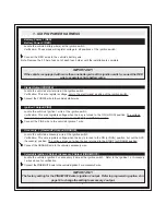
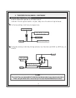
1.  SIX PIN POWER HARNESS

Battery  Power 1 (RED)
Battery Power 2 (RED)

Locate the vehicle battery wire(s) at the ignition switch.
Verification:  These wires will register voltage in all positions of the ignition switch.

Connect the RED wires to the vehicle’s battery wire.

Note: Remove the 30 Amp fuse out of each fuse holder until the installation is complete

IMPORTANT!

  If the vehicle is equipped with more than one battery wire at the ignition switch, connect the RED

wire to separate vehicle battery wires.

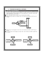
Starter Output (PURPLE)

Locate the vehicle’s starter wire at the ignition switch.

Verification: This wire registers voltage only in the start (crank) position of the ignition switch.

Connect the PURPLE wire to the vehicle’s starter wire.

Ignition 1 Output (PINK)

Locate the vehicle’s Ignition 1 wire at the ignition switch.

Verification: This wire registers voltage when the key is turned to the ON (or RUN) position. The voltage
does not drop out when the key is turned to the START (or CRANK) position.

Connect the PINK wire to the vehicle’s Ignition 1 wire.

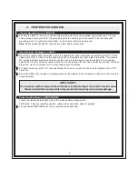
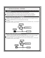
Accessory  1 (Heater/AC) Output (ORANGE)

Locate the vehicle’s accessory wire at the ignition switch.

Verification: This wire registers voltage when the key is turned to the ON (or RUN) position, but not the ACC
(Accessory) position. The voltage drops out when the key is turned to the START (or CRANK) position.

Connect the ORANGE wire to the vehicle’s accessory wire.

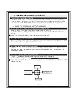
Selectable Ignition 2 Output / Accessory 2 Output (PINK/WHITE)

Locate the vehicle’s ignition 2 or accessory 2 wire at the ignition switch.  Refer to the Ignition 1 or Accessory
1 wires above for verification.

Connect the PINK/WHITE wire to the vehicle’s ignition 2 or accessory 2 wire.

IMPORTANT!

The factory setting for the PINK/WHITE wire is ignition 2 output.  Refer to programming option 2 on

page 14 to change the setting to accessory 2 output.

Summary of Contents for CA 521

Page 1: ...ust accept any interference received including any interference that may cause undesired operation Warning Changes or modifications not expressly approved by the party responsible for compliance could void the user s authority to operate the equipment CA 521 Installation Instructions Kit Contents 1 CA 521 Control Module 2 4 Button High Frequency Transmitters 1 Receiver with Pushbutton and LED 1 Mu...

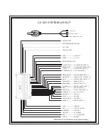
Page 2: ...MED OUTPUT PURPLE WHITE TACH INPUT BLACK GROUND RED WHITE TRUNK BLUE BLACK ACTIVE OUTPUT GRAY BLACK WAIT TO START INPUT GRAY HOOD PIN INPUT BLACK WHITE NEUTRAL SAFETY INPUT ORANGE RED DEFROST OUTPUT BROWN RED BRAKE INPUT WHITE PARKING LIGHT OUTPUT WHITE RED PARKING LIGHT POLARITY ORANGE BLACK PARKING BRAKE INPUT GREEN LOCK LT GREEN BLACK FACTORY DISARM LT BLUE PULSE AFTER START GREEN WHITE PULSE A...

Page 3: ...fication This wire registers voltage when the key is turned to the ON or RUN position The voltage does not drop out when the key is turned to the START or CRANK position Connect the PINK wire to the vehicle s Ignition 1 wire Accessory 1 Heater AC Output ORANGE Locate the vehicle s accessory wire at the ignition switch Verification This wire registers voltage when the key is turned to the ON or RUN...

Page 4: ...h away from rain gutters or for mounting against the fire wall Carefully check behind the chosen location for fluid lines or electrical wiring The hood pin switch must be mounted into a metal chassis ground surface For direct mounting drill a 1 4 hole and thread the hood pin switch into the hole and tighten with a 7 16 nut driver Route the GRAY wire through an existing grommet if available in the ...

Page 5: ...ing light output wire at the vehicle s light switch Ground When Armed Output 300mA ORANGE This wire will show Ground when the system is Armed This wire is used for controlling window modules or additional sensors Tach Signal Input PURPLE WHITE Locate the vehicle s ignition coil or fuel injector in the engine compartment Verification Refer to Vehicle Wire Color and Location Chart for the wire color...

Page 6: ...cuits follow the diagram below Use Code Alarm part HDRLY an SPDT relay not included NOTE The CA 521 has an optional Wait To Start feature that provides a pre set wait to start time When using this feature it is not necessary to connect the GRAY BLACK wire above GRAY BLACK Diesel Wait To Start Wire Vehicle Control Module Ground Wait To Start Bulb At Instrument Panel 1N4004 Diode 30 87 87a 86 85 Veh...

Page 7: ...n SPDT relay not included Ignition 3 output see the diagram on the left below Use Code Alarm part HDRLY an SPDT relay not included Accessory 2 3 output see the diagram on the right below Use Code Alarm part HDRLY an SPDT relay not included Fused 12 Volt Battery Source 30 87 87a 86 85 BLUE BLACK ActiveOutput Wire VATS Control Module Matching Value Resistor Ignition Switch VATS Wire 1 WHITE or WHITE...

Page 8: ...wire to the vehicle defrost wire if the system is negative If the system is positive connect the ORANGE RED wire as shown in the diagram below Use Code Alarm part HDRLY an SPDT relay not included Trunk Release Output 300mA RED WHITE Locate the vehicle s trunk release wire at the trunk release switch Verification This wire will register either positive voltage or ground when the trunk release is ac...

Page 9: ... to prevent the vehicle s accessories from staying on after remote start shutdown Pulse During Crank 300mA BLACK YELLOW Locate the vehicle s second starter crank wire at the ignition switch If equipped Verification This wire registers voltage only in the start crank position of the ignition switch Connect the BLACK YELLOW wire as shown in the diagram below Use Code Alarm part HDRLY an SPDT relay n...

Page 10: ...hen the lock unlock switches are activated Connect the GREEN and BLUE wires shown in the diagram below Reverse Polarity 5 Wire Door Locks Locate the lock unlock wires at the vehicle s lock unlock switch Verification These wires will rest at ground and register positive voltage when the lock unlock switches are activated Connect the GREEN and BLUE wires shown in the diagram below Use Code Alarm par...

Page 11: ...ation chart for specific resistor values and polarity for your vehicle Connect the GREEN and BLUE wires shown in the diagram below Use Code Alarm part HDRLY an SPDT relay not included Aftermarket door lock unlock actuators not supplied use Code Alarm part DA1 Connect the GREEN and BLUE wires shown in the diagram below Use Code Alarm part HDRLY an SPDT relay not included 30 87 87a 86 85 Fused 12 Vo...

Page 12: ...Transponder Databus Interfaces to communicate with the vehicle s Databus When using the DBI port to control the Code Alarm Door Lock and Transponder Interface modules the following options may be available Please refer to the D2D Data to Data function list available per vehicle on the tech service web site Tach Input Brake Safety Shut Down Trunk Hatch Open Diesel Glow Plug Input Door Lock Control ...

Page 13: ...TANT IF YOU ALLOW MORE THAN 15 SECONDS TO PASS BETWEEN STEPS THE PROGRAMMING MODE WILL BE TERMINATED Programming Tach Rate 1 Enter the vehicle and turn the ignition key to the ON position 2 Press and release the programming switch 3 times 3 Immediately turn the ignition key to the OFF position 4 Push and hold the programming switch 5 Start the vehicle using the ignition key while continuing to hol...

Page 14: ...ating the feature setting see chart below IMPORTANT IF YOU ALLOW MORE THAN 15 SECONDS TO PASS BETWEEN STEPS THE PROGRAMMING MODE WILL BE TERMINATED OPTION PROGRAMMING CHART FEATURESELECTION 1 FLASH 2 FLASH 3 FLASH 4 FLASH DEFAULT 1 Run Time 5 Min 10 Min 15 Min 20 Min 10 Min 2 Ign 2 or Acc 2 ACC 2 Ign 2 Ign 2 3 Parking Lights Steady Flash Steady 4 Tach Mode Tachless Tach DBI Input Tach 5 Voltage Le...

Page 15: ...m fails this test recheck your hood pin switch connection to the GRAY wire Warning Do not use the remote start system until you confirm operation of the hood pin safety shutdown Brake Safety Shutdown The Brake Safety Shutdown is to shutdown the remote start system if the brake pedal is pressed To test the integrity of this circuit 1 Sitting in the driver s seat remote start the vehicle using the t...

Page 16: ...16 ...

Reviews: