background image

15

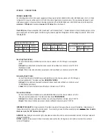
Multi-Functional Intersection Control System - This system allows multiple lighting options with a single pair of intersection lights. The
control  center of  the system is the Multi-Functional Control Module located in the lower section of the light bar. This combined with the
Sensing Lighthead Assemblies, located in the front lower section,  allows the operator to select (4) four modes of operation - intersection,
driver side alley, passenger side alley and takedown positions.

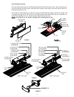
Sensing Lighthead Assembly  - As with the standard intersection lights, these are high intensity 120 degree oscillating light assem-
blies. With addition of the Position Sensing module these lights can be placed in the takedown or alley positions. (Figure 11)
Note: If the gear assembly is replaced, care must be taken to insure that the flat nylon washer is seated between the gear and the
bottom plate to prevent premature wear and failure.

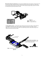
Multi-Functional Control Module - Using

standard lighting controls the operator can select the
operation of the Lighthead assemblies.

                   Figure 11

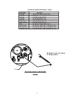
S50690 - Driver side assembly
S50691 - Passenger side assembly

S55401 - Multi-Functional Control Module

* - see wire tag for

exact wire color code.

Figure 12

WIRE

FUNCTION

GRN

ALLEY

BLK

GROUND

YEL

TAKEDOWN

RED

POWER

Summary of Contents for CODE 360

Page 1: ...quipment IMPORTANT CODE 360 TRI LEVEL LIGHT BAR CONTENTS For future reference record your lightbar s serial no here __________________________________________ Introduction 2 3 Unpacking Pre Installati...

Page 2: ...rning signal Never take the right of way for granted It is your responsibility to be sure you can proceed safely beforeenteringanintersection drivingagainsttraffic respondingatahighrateofspeed orwalki...

Page 3: ...erformanceofthesystem B Placethecontrolswithinconvenientreachoftheoperatorsothathecanoperatethe systemwithoutlosingeyecontactwiththeroadway Emergencywarningdevicesoftenrequirehighelectricalvoltagesand...

Page 4: ...heimpropernumberof screwsmayresultinlossofwarrantycoverageontheequipment WARNING Mounting Bracket Bottom of Lightbar 5 16 Split Lockwasher Rubber Feet 5 16 Nut FIGURE 1 Hook on Mounting Begintheinstal...

Page 5: ...16 trimnut sightly Permanent Mounting Typical Mounting Refer to Figure 3 Place the light bar upside down on a table or other work surface being careful not to scratchthelenses Slidethe 5 16 carriagebo...

Page 6: ...connectionsandsplicestoprotectthesepointsfromcorrosionandlossof conductivity Groundterminationsshouldonlybemadetosubstantialchassiscomponents preferablydirectlyto thevehiclebattery Theusershouldinstal...

Page 7: ...r each module the instantaneous peakcurrenttoamodulecanbesignificantlyhigherduringlowvoltageconditions ToavoidprematurelyblowingATOstylefusesor trippingbreakersitisrecommendedthefollowingrule of thumb...

Page 8: ...e DIM setting to assure that motorists can clearly see the emergency vehicle WARNING For safety purposes the corner modules in lightbars are not connected to the dimming circuit This ensures that when...

Page 9: ...Flash Three Pulses per flash 70 fpm Quad Pop Flash Four Pulses per flash 3 equal 1 extended 70 fpm Bothheadswillbeinthemodeselected BothheadswillflashtogetherunlessinFrontCut offmode LED DIRECTIONAL M...

Page 10: ...Pulses per flash 70 fpm Double Flash Two Pulses per flash 70 fpm Fast Double Flash Two Pulses per flash 85 fpm NFPA Four Pulses 70 Duty Cycle 75 fpm Quad Pop Flash Four Pulses per flash 3 equal 1 ext...

Page 11: ...2 VDC through a user supplied switch This mode overrides REAR ONLY MODE 4 6 Head Front and Rear inboard and outboard strobes on each side will flash at a minimum rate of 70FPM flashesperminute 2 Head...

Page 12: ...nsestocarwashesthatuse brushes asthesewillscratchthelenses Lens Removal First disengagethelensclips 4 per lens as shown in Figure 6 Finally insert a screwdriver into the inside edge or corner of the l...

Page 13: ...g assemblies WARNING Highvoltagesand ortemperaturesarepresentinsidetheunit Disconnectfrompowerandwait10minutes prior to servicing or troubleshooting Use hand and eye protection when changing halogen l...

Page 14: ...semblyfromthelightbarasaunit Toreinstallthepowersupplyreversetheabovesteps Caution Verify that wires are not pinched or damaged when reinstalling power supply FIGURE 8 FIGURE 10 FIGURE 9 MAXIMUM 27W 4...

Page 15: ...these are high intensity 120 degree oscillating light assem blies With addition of the Position Sensing module these lights can be placed in the takedown or alley positions Figure 11 Note If the gear...

Page 16: ...rness No power to control module Check 12VDCswitchingcontrol Failedlightheadassembly Replacelightheadassembly Failedcontrolmodule Replacecontrolmodule Lighthead operates properly Lampburntout Replacel...

Page 17: ...1 7 CODE 360 EXPLODED VIEW 6 9 10 11 13 7 8 4 5 3 1 2...

Page 18: ...1 8 2 3 2 4 FIGURE 13 12 15 16 18 17 14 20 21 22 19...

Page 19: ...atorMotorAssy50WBayonetStdSpeed S95980 RotatorMotorAssy50WBayonetFastSpeed S95981 RotatorMotorAssy24V S95982 10 RotatingFilter Green S95988M Red S95989M Blue S95990M Amber S95991M 2 4 Code 360 1 2 Cyl...

Page 20: ...y Light PASS S50864 19 Halogen Lower Light Head Filter Green T05170 Clear T05171 Red T05179 Blue T05173 Amber T05174 Code 360 External D O T Strip Assembly S50838M Code360 Stop Turn TailLightW Adapter...

Page 21: ...w for information on repair and trouble shooting Additionalinformationmaybeobtainedfromthefactorytechnicalhelplineat314 426 2700 ext 2131 NO STROBE LIGHTS IN THE LIGHTBAR OPERATE Check the following 1...

Page 22: ...a Defective lamp b Low voltage c Poor ground d Product is in Dim mode SOLUTION a Reconnectplug b Reconnect ground a Check connections at the battery and plug If connections are good and voltage is at...

Page 23: ...2 3 NOTES...

Page 24: ...ythiswarranty Code3 Inc shallinnoway beliableforotherdamagesincludingconsequential indirectorspecialdamageswhetherlossisduetonegligenceorbreach ofwarranty CODE 3 INC MAKES NO OTHER EXPRESS OR IMPLIED...

Reviews: