10
M a v e r i c k B o a t C o m p a n y , I n c .
•
3 2 0 7 I n d u s t r i a l 2 9 t h S t .
•
F o r t P i e r c e , F l o r i d a 3 4 9 4 6
•
( 7 7 2 ) - 4 6 5 - 0 6 3 1 o r
( 8 8 8 ) - s h a l l o w
•
F a x : ( 7 7 2 ) 4 8 9 - 2 1 6 8
SYSTEMS
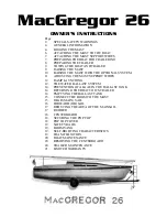
THE LIVEWELL PUMP
ASSEMBLY IN THE
“OPEN
POSITION
Ball Valves
Ball valves can be used to serve several purposes. They
allow seawater to enter the boat, in the case of livewells,
and they also act as a safeguard to stop water from
entering. To tell which position a ball valve is in, open or
closed, look at the valve and determine the direction of
flow. When the ball valve handle is in the same position as
the direction of flow, the valve is in the
“OPEN” position.
When the ball valve handle appears to cross the direction
of flow, the valve is in the
“CLOSED” position.
280 Deck Drain System
The deckdrain system is equipped with 1
1/2” thru hull
fittings through the aft port and starboard hull sides. These
fittings have to be installed lower than the drains in the
cockpit floor so that gravity will allow the cockpit to drain
free of water. This puts these fittings very close to the water
line of the hull. These drains are rigged with ball valves that
can be opened and closed to control the flow of water. The
ball valves can be accessed through the pie eyes on the
port starboard side of the transom. In the open position,
these ball valves will allow water to flow freely from the
cockpit, thus making the boat
“self-bailing”. When closed,
no water will be allowed to travel to or from the cockpit.
Refer to page 34 for the Deck Drain System Diagram.
280 Livewell Pump Assembly
The livewell pump assembly is composed of a scoop
strainer mounted to the bottom of the hull, a thru hull fitting,
ball valve assembly, and the pump. As you can see, the
ball valve assembly is in the
“OPEN” position. This is the
correct position for the operation of the livewell system.
Water Flow
OPEN