


16 of 21
Pneumatic chain hoist CPA ATEX
8.9 PNEUMATIC CHAIN HOIST MAINTENANCE IN GENERAL
In particular check following parts:
• Threaded connections in general
Check all nuts, screws and locking devices for tightness.
• Chain container
Ensure that it is securely fastened. Check for cracks or wear.
• Supporting pin
(Connection between chain hoist and top hook or trolley)
Check for cracks and wear, and tightness of the safety.
3. Full dismantling
After taking out all the inner parts of the motor as described in 1, and
pulling out the sealing plates (items 5 and 20) from the rotor seats, remov-
ing the cylinder sockets (item 9) and lamellae (item 17), the grooved ball
bearing (items 6 and 21) can be taken out of the sealing plates (items
5 and 20) if necessary, after loosening the safety rings (items 7 and
22). The whole control valve must be detached from the motor housing
(item 1). The complete brake (items 40-54) can be separated from the
motor housing (item 1) after loosening the screws (item 55). The o-ring
(item 29) and the sealing shim (item 30) with the radial shaft sealing
ring (item 31) must be taken out of the motor housing. The silencers
(item 2) normally remain in the motor housing (item 1) and are replaced
only if they are damaged.
The fully stripped brake was disassembled as already partially described
in section 2. After removing the locking ring (item 52) the pressure plate
(item 51) is to be pulled out of the brake air piston (item 49) and it is
to be taken out of the brake air housing (item 46). If the shuttle valve
function in the brake housing (item 40) is faulty, the spacer screws (item
42) must be loosened and the control piston of the brake ventilation
(item 41) must be taken out.
Assembly
Installation takes place essentially in the reverse order of the dismantling.
Please ensure correct distancing for the motor.
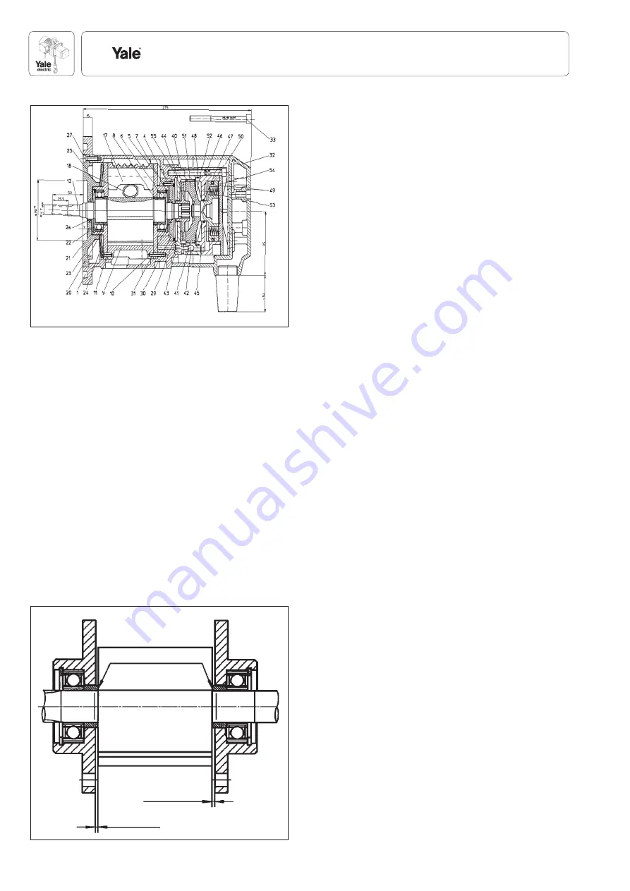
The “longitudinal clearance” between the rotor (item 12) and the sealing
plates (items 5 and 20) should be approx. 0.04 mm (Fig. 22).
The edges of openings in the spacer rings (item 8 and item 23) must
point to the rotor centre.
Before inserting the lamellae (item 17), clean the rotor slots of oil and
resin residues. The new lamellae should easily fall into the slots. The
ball bearings (items 6 and 21) are to be re-greased.
Attention:
If the ball bearings have been replaced (items 6 and 21), the
spacing is to be re-adjusted (see Fig. 22). The ball bearing inner rings
must be pressed on to the locking ring without any clearance in order
to adjust the spacer rings (items 8 and 23) (new spacer rings must
always be adjusted).
After fastening the motor lid (item 25), turn the rotor (item 12) slightly
by hand. If the rotor (item 12) is rigid or it cannot be turned, a “seating
blow” on the motor housing (item 1, laterally or in the axial direction
with a rubber hammer) is most helpful in bringing the rotor (item 12)
to a free run position. The sealing shim (item 30) is then fastened to
the shaft sealing (item 31). Pay attention to the sealing lips! Load the
O-ring (item 29) and insert the brake housing (item 40) with shuttle
valve in the motor housing. Do not forget the O-rings (item 43). Apply a
rust protection paste as described above (on rotor pin (item 12), in the
brake housing (item 40) and the brake disc (item 44)). Slide the brake
disk (item 44) on and check for easy seat. Pre-install the brake air pis-
ton (item 49) and the pressure plate (item 51) in the brake air housing
(item 46). Provide the movement seats with rust protection paste here,
too. Then install the brake housing (40). Insert the pressure springs
(item 53), the centre brake housing lid (item 54) and fasten the brake
complete with screws (item 55). Mount the motor housing lid (item 32)
and tighten with screws (item 33).
Flange the control and test the motor functions.
Due to the asymmetrical design, the running noise and the idle run
speeds for clockwise and anti-clockwise rotation are diff erent. The
specifi ed values (see Table on Page 9) are always related to the hoist/
lifting side. The brake function, i.e. the opening and stopping during air
impact is to be tested, to prevent a continuous grinding of the brake disc.
A minimum pressure of 2.6 bar is necessary for this.
Edge failure
approx. 0.04
approx. 0.04
Fig. 22
Fig. 21


