


10 of 21
Pneumatic chain hoist CPA ATEX
7. OPERATION
Installation, service, operation
Operators delegated to install, service or independently operate the hoist
must have had suitable training and be competent.
They must be authorized by the company for setting up, main-
taining or operating the equipment. In addition, the operator
must be familiar with UVV regulations (for accident prevention).
5. FUNCTION CHECK AFTER INSTALLATION
Prior to operating the hoist, grease the trolley pinions (geared trolley,
compressed air trolley) and lubricate the load chain when it is not under
load (see the table on page 11).
Before the chain hoist is put into regular service, following additional
inspections must be made:
• Are all screwed connections on the hoist and trolley fully tightened
and secure?
• Are the end stops on the trolley runway in place and secure?
• Is the chain drive correctly reeved?
• The chain end stop must be connected to the free (idle) chain strand
(see Fig. 1 - chain end stop).
• All units equipped with two or more chain strands must be inspected
before each initial operation to ensure that the load chain is not twisted
or kinked. The chains of 2-strand hoists may become twisted if the
bottom block is rolled over.
• Perform an operation cycle without load. The chain should move in a
steady, smooth way. Check the function of the sliding clutch by moving
the bottom block against the housing (max. 5 s).
• Check the brake function when lifting and lowering with rated load.
The braking distance must not be more than 50 mm.
• Drive trolleys through the entire length of the run without a load. When
doing so, there must be lateral play between the plain roller and beam
fl ange between 2 and 4 mm on each side. Check that beam end stops
are positioned correctly and secure.
6. INITIAL
OPERATION
Inspection before initial operation
Before fi rst use, all hoisting equipment must be subjected to testing
by a qualifi ed person and any defi ciencies corrected. The inspection
mainly consists of a visual inspection and a function check. The checks
should guarantee that the unit is in a safe condition and if necessary,
faults and damages caused by e.g. improper transport or storage can
be identifi ed and remedied.
Competent persons may be, for example, the maintenance engineers of
the manufacturer or the supplier. However, the company may also entrust
the inspection to its own appropriately trained specialist personnel. The
inspections have to be initiated by the operating company.
Inspection by a crane expert
If the lifting device is used as a crane, it has to be inspected and ap-
proved by a crane expert before initial operation. This inspection has to
be registered in the crane inspection book. The inspection by the crane
expert has to be instigated by the operating company.
Inspection before starting work
Before starting work inspect the hoist/trolley, chains, all load bearing
components and supporting structure every time for visual defects. In
addition also test the brake and check that the hoist and the load are
correctly attached. To do this, use the unit to lift a load and lower it
again only over a short distance. Selection and calculation of the proper
suspension point and supporting structure are the responsibility of the
operating company.
Inspection of the load chain
Inspect the load chain for suffi
cient lubrication and check for external
defects, deformations, superfi cial cracks, wear and corrosion marks.
Inspection of chain end stop
The chain end stop must be connected to the free (idle) chain strand
(see Fig. 1 - chain end stop).
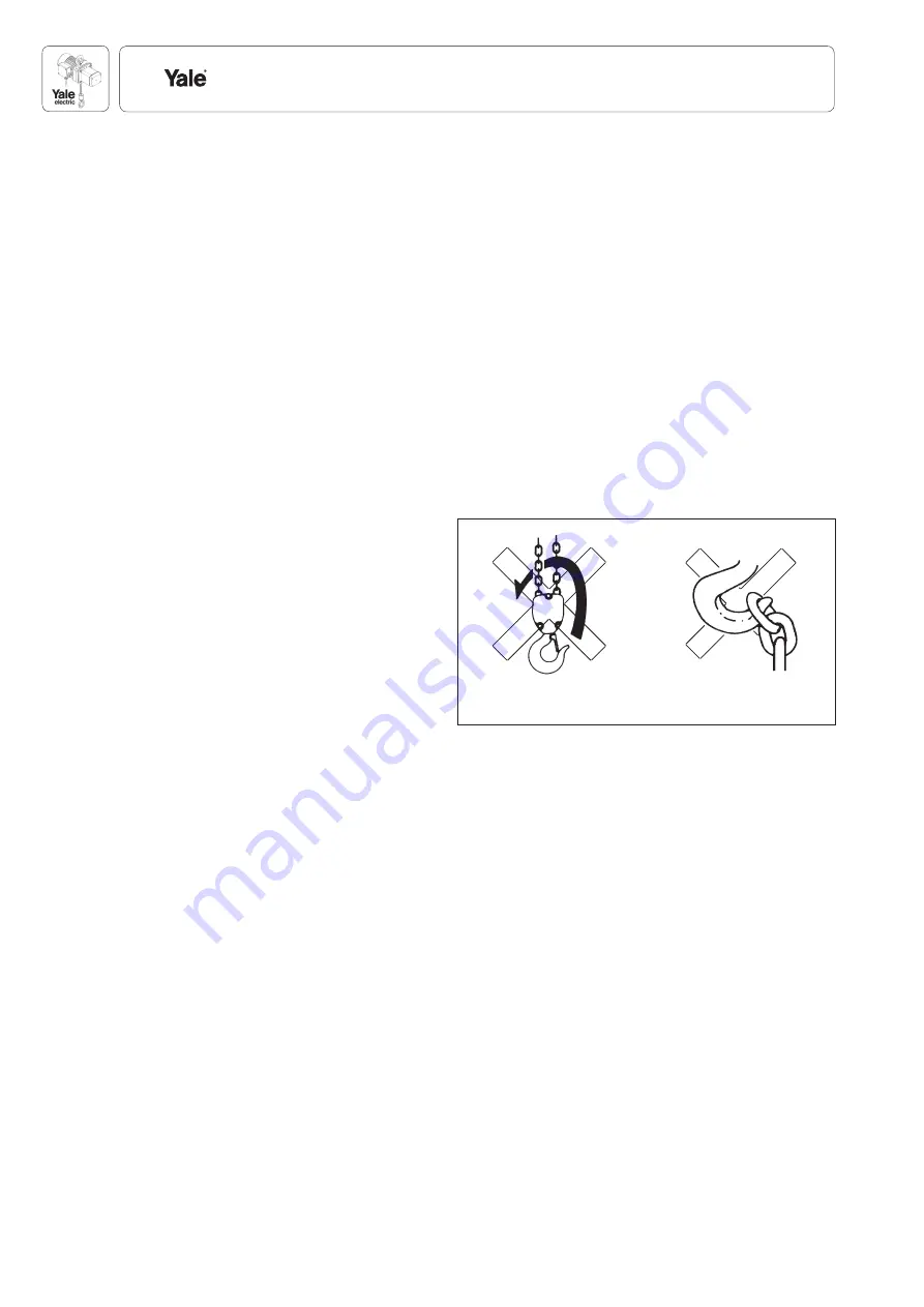
Inspection of the chain reeving
All units equipped with two or more chain strands must be inspected
before each initial operation to ensure that the load chain is not twisted
or kinked. The chains of 2-strand hoists may become twisted if the bot-
tom block was rolled over (Fig. 14).
Inspecting the load hook and the top hook
Check the load hook and the top hook for deformations, cracks, dam-
ages, abrasion and signs of corrosion.
Suspending the load
The load must always be seated in the centre of the hook. Never attach
the load to the tip of the hook (Fig. 15). This also applies to the top hook.
Inspect the beam (for trolleys)
Inspect the beam for correct assembly and visually check for external
defects, deformations, superfi cial cracks, wear or signs of corrosion.
Especially make sure that the locking sleeves are properly fi tted to the
centre beam (Fig. 11).
Check adjustment of trolley width
On chain hoists with trolley (CPA-VTP/G/E), check that the clearance
between the plain roller fl ange and the beam outer edge is equal on both
sides and within the tolerances given (see page 7, Fig. 11). Enlarging
the clearances, e.g. to enable the trolley to negotiate tighter curves, is
forbidden.
Traversing the lifting device
Plain trolley:
By pushing on the suspended device (e.g. lifting device) or the attached
load.
Attention:
Never pull the compressed air hoses. Suspended loads may
only be pushed.
Fig. 14
Fig. 15


