


Pneumatic chain hoist CPA ATEX
15 of 21
Parts subject to wear are:
Stop washers (item 6, 23, 30), needle bearings (item 8, 24, 31), O-rings
and packing rings (item 4, 16, 18, 43) as well as the seal (item 45).
Assembly
Installation should be performed only on the basis of the sectional
drawing. Installation takes place essentially in the reverse order of the
dismantling.
Special care should be taken for clean and correct installation of planet
gears (item 7) with needle bearings (item 8) in equal sorting and stop
washers (item 6) as well as spacer rings (item 9) in the planet gear
carrier (item 3).
The brake friction pads (item 28) on either side of the ring gear (item 29)
must be installed oil-soaked (leave in oil for 1 hour before installation).
The exact adjustment of the overload device is only possible when the
lifting device is completely reassembled. Pre-adjustment of the cup
spring (item 41) is made with the fi xing screw (item 42). After the exact
adjustment has been made, the fi xing screw (item 42) is secured by
means of the ball (item 46) and the threaded pin (item 47).
The gearbox is to be fi lled with approx. 0.3 Litre of gearbox oil
(CLP 460, DIN 51547).
Afterwards the fi ll hole can be closed with the screw plug (item 44) and
the seal (item 45).
8.8 MAINTENANCE OF THE MOTOR
Motor
The life and performance of the hoist motor are properly determined by:
a) the purity of the air
b) the lubrication conditions and maintenance
to a) If rust can form and water can settle in the supply pipe, dirt and
water separators should be installed upstream.
to b) resin- and acid-free lubricating oils (SAE 5W - SAE 10W) should
always be used. Viscous oils stick to the lamellae and aff ect the starting
and effi
ciency of the motor. The lifespan can be signifi cantly increased
through optimum lubrication. We therefore recommend the prefi xing of
maintenance units and oils.
The oilers should be set in such a way that for every m
3
/min. of air
consumption, approx. 2-5 drops are sprayed.
Wear parts - especially the lamellae - should be replaced at the right
time. They are worn out when their width is less than 25 mm (Fig. 19).
The rings (item 18) working as start-up aids must also be replaced with
the lamellae.
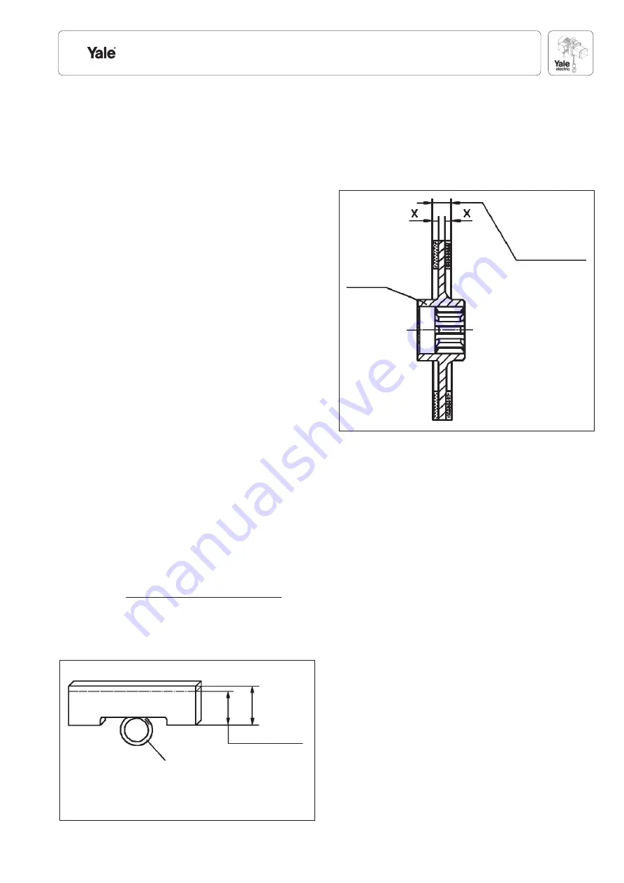
O-Ring
The main wear parts include the brake disk (item 44). The thickness of
the brake lining must be regularly checked, as wear of the lining aff ects
the retention force.
The brake disk is to be changed when the lining thickness is less than
7.5 mm or the lining has worn out on one side and falls below the
dimension x = 2 mm (Fig. 20).
Disassembly and assembly
Dismantling - lamellae and brake disc change
1. Changing lamellae
Loosen the screw (item 27), remove the motor cover (item 25) and cup
spring (item 24). Pull out the sealing plate with the clutch bearing (item
20) from the rotor seat using an extraction device, remove the spacer
ring (item 23). Remove the lamellae (item 17) from the rotor slots.
If no extraction device is available, the complete inner parts can also
be taken out of the motor housing and dismantled further on the work-
bench. To detach the sealing plates (items 5 & 20) from the rotor seat,
slightly pressing a wooden board on to the shaft ends may be helpful.
The cylinder socket (item 9) can be removed and the lamellae (item 17)
can be taken out of the rotor slots.
Before replacing the lamellae, clean the rotor slots of oil and resin resi-
dues. The new lamellae must easily fi t into the slots of the rotor (item 12).
2. Replacing brake discs
Loosen the screws (item 33) and remove the motor housing lid (item
32). Remove the springs (item 55).
Attention:
The pressure springs (item 53) are under tension.
Remove the brake housing lid (item 54) and the pressure springs (item
53). Pull out the brake air housing (item 46) complete with (item 47-
52) from the brake housing (item 40). Pay attention to the O-ring (item
45). Pull out the brake disc (item 44) from the rotor pin and check the
thickness of the lining.
Before the installation/assembly, the brake housing (item 40) and the
pressure plate (item 51) must be cleaned of brake dust. The shaft end
of the rotor (item 12, splining) as well as the hole of the brake disc (item
44) must be coated with a rust protection paste (e.g. Altemp Q NB 50)
to guarantee mild movement of the brake disc (item 44) on the rotor pin
(item 12). This also applies to the teething of the pressure plate (item
51) and the brake housing (item 40).
Fig. 20
Fig. 19
< 25 mm change
Brake disc assembly
Installation 9 mm
< 7.5 mm change
x installation 3 mm
< 2 mm change
31.9 mm
Installation
measurement


