18
00001996 (REV AC) 627NH
October 2014
INSPECTION
To maintain continuous and satisfactory operation, a regular
inspection procedure must be initiated to replace worn or
damaged parts before they become unsafe. Inspection intervals
must be determined by the individual application and are based
on the type of service to which the hoist will be subjected.
The type of service to which the hoist is subjected can be
classifi ed as “Normal”, “Heavy”, or “Severe”.
Normal Service:
Involves operation with randomly distributed loads within
the rated load limit, or uniform loads less than 65 percent of
rated load for not more than 25 percent of the time.
Heavy Service:
Involves operating the hoist within the rated load limit which
exceeds normal service.
Severe Service:
Normal or heavy service with abnormal operating conditions
or constant exposure to the elements of nature.
Two classes of inspection - frequent and periodic - must
be performed.
Frequent Inspections:
These inspections are visual examinations by the operator or
other designated personnel. Records of such inspections are
not required. The frequent inspections are to be performed
monthly for normal service, weekly to monthly for heavy
service, and daily to weekly for severe service, and they
should include those items listed in Table 4.
Periodic Inspections:
These inspections are visual inspections of external
conditions by an appointed person. Records of periodic
inspections are to be kept for continuing evaluation of the
condition of the hoist.
Periodic inspections are to be performed yearly for normal
service, semi-annually for heavy service and quarterly for severe
service, and they are to include those items listed in Table 5.
CAUTION: Any defi ciencies found during inspections are to
be corrected before the hoist is returned to service. Also,
the external conditions may show the need for disassembly
to permit a more detailed inspection, which, in turn, may
require the use of nondestructive type testing
PREVENTATIVE MAINTENANCE
In addition to the above inspection procedure, a preventive
maintenance program should be established to prolong
the useful life of the hoist and maintain its reliability and
continued safe use. The program should include the periodic
and frequent inspections with particular attention being
paid to the lubrication of the various components using the
recommended lubricants (see page 127).
SUSPENSION INSPECTION CRITERIA
BRACKETS - Replace any bracelets found to be cracked or distorted.
BOLTS - If the suspension is removed for any reason, including
inspection, the suspension bolts should be replaced.
NYLON THREAD LOCKING NUTS - It is not necessary to replace
the nylon thread locking nuts each time the suspension bolts are
replaced as long as new bolts with the locking patch are being used.
It is recommend that the nylon thread locking nuts are replaced each
time the hoist is torn down to allow these nuts to be replaced.
HOOK REMOVE CRITERIA
Based on B30-10 Hooks shall be removed from service if
damage such as the following is visible and shall only be
returned to service when approved by a qualifi ed person:
a.
Missing or illegible rated load identifi cation or illegible
hook manufacturers’ identifi cation or secondary
manufacturer’s identifi cation.
b.
Excessive pitting or corrosion.
c.
Cracks, nicks, or gouges.
d.
Wear--any wear exceeding 10% of the original section
dimension of the hook or its load pin.
e.
Deformation--any visibly apparent bend or twist from the
plane of the unbent hook.
f.
Throat opening-any distortion causing an increase in the
throat opening of 5% not to exceed ¼” (6mm).
g.
Inability to lock - any self-locking hook that does
no lock.
h.
Inoperative latch any damaged latch or malfunctioning
latch that does not close the hook’s throat.
i.
Thread wear, damage, or corrosion.
j.
Evidence of excessive heat exposure or
unauthorized welding.
k.
Evidence of unauthorized alterations such as drilling,
machining, grinding, or other modifi cations.
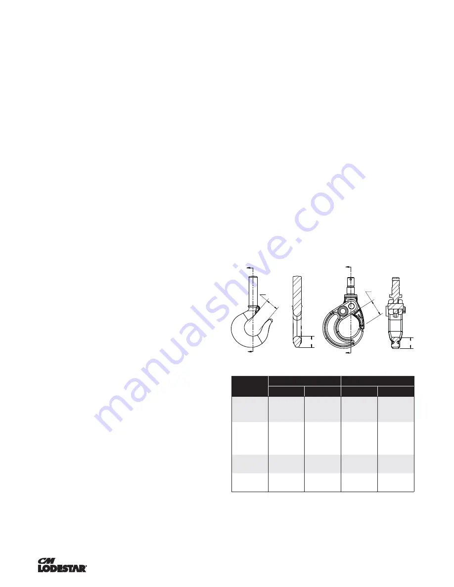
Figure 14. Hook Inspection
Models
Latch Type Hook
Latchlok
®
Hook
"A" Max
"B" Min
"A" Max
"B" Min
A, A-2, AA, AA-2,
B, B-2, C, C-2, F
AND F-2
1.19"
(30.2mm)
.91"
(23.1mm)
1.48"
(37.7mm)
.75"
(18.8mm)
E, E-2, H, H-2,
J, J-2, JJ, JJ-2,
L, L-2, LL AND
LL-2
1.31"
(33.3mm)
1.08"
(27.5mm)
1.48"
(37.7mm)
.75"
(18.8mm)
R,R-2, RR, RR-2
AND RRS
1.50"
(38.1 mm)
1.43"
(36.2mm)
1.92"
(48.8mm)
.94"
(23.9mm)
RT, RT-2, RRT
AND RRT-2
1.50"
(38.1 mm)
1.43"
(36.2mm)
2.50"
(63.5mm)
1.19"
(23.9mm)
"A" MAX.
A
A
"B" MIN
"A" MAX
B
B
"B" MIN
Section A-A
Section B-B
Summary of Contents for Lodestar A
Page 31: ...31 00001996 REV AC 627NH October 2014 REFERENCE WIRING DIAGRAMS ...
Page 32: ...32 00001996 REV AC 627NH October 2014 REFERENCE WIRING DIAGRAMS ...
Page 33: ...33 00001996 REV AC 627NH October 2014 REFERENCE WIRING DIAGRAMS ...
Page 34: ...34 00001996 REV AC 627NH October 2014 REFERENCE WIRING DIAGRAMS ...
Page 35: ...35 00001996 REV AC 627NH October 2014 REFERENCE WIRING DIAGRAMS ...
Page 36: ...36 00001996 REV AC 627NH October 2014 REFERENCE WIRING DIAGRAMS ...
Page 37: ...37 00001996 REV AC 627NH October 2014 REFERENCE WIRING DIAGRAMS ...
Page 38: ...38 00001996 REV AC 627NH October 2014 REFERENCE WIRING DIAGRAMS ...
Page 39: ...39 00001996 REV AC 627NH October 2014 REFERENCE WIRING DIAGRAMS ...
Page 40: ...40 00001996 REV AC 627NH October 2014 REFERENCE WIRING DIAGRAMS ...
Page 41: ...41 00001996 REV AC 627NH October 2014 REFERENCE WIRING DIAGRAMS ...
Page 42: ...42 00001996 REV AC 627NH October 2014 REFERENCE WIRING DIAGRAMS ...
Page 43: ...43 00001996 REV AC 627NH October 2014 REFERENCE WIRING DIAGRAMS ...
Page 44: ...44 00001996 REV AC 627NH October 2014 REFERENCE WIRING DIAGRAMS ...
Page 45: ...45 00001996 REV AC 627NH October 2014 REFERENCE WIRING DIAGRAMS ...
Page 46: ...46 00001996 REV AC 627NH October 2014 REFERENCE WIRING DIAGRAMS ...
Page 95: ...95 00001996 REV AC 627NH October 2014 NOTES ...
Page 127: ...31 P N 10001609 REV AB 627NH December 2014 Notes ...


