26
P/N: 10001609 (REV AB) 627NH
December 2014
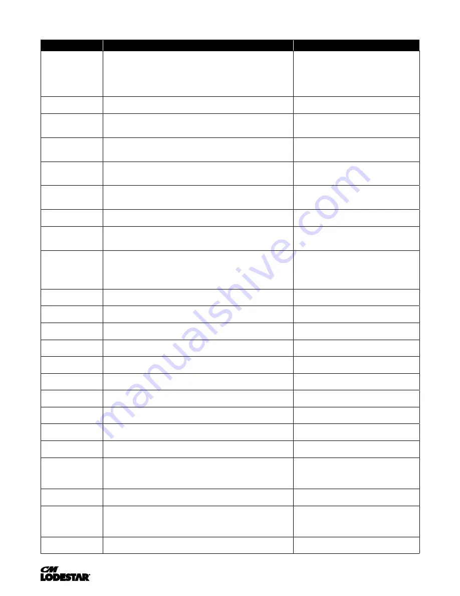
FACTORY SETTINGS OF PARAMETERS
FAULT CODE
FAULT OR INDICATOR NAME/DESCRIPTION
CORRECTIVE ACTION
BB
(flashing) Base Block
External Base Block Indicator.
The flashing base block signal is the result of
a multi function input in the terminal strip. The base block indicates that the
drive’s IGBTs have been disabled. The motor will begin coasting when the base
block input is received. If a
RUN
command is still present when the
BB
signal is
removed, the output voltage will be restored to the previous operating level and
operation will continue at the previously commanded frequency.
1. Check constants H01.01 through H01.07
for proper programming.
2. Check terminal status. (U01.10)
BEO
(flashing) Brake
Ans Lost
Brake Answer back signal is lost during run.
While running, the multi-function
input brake answer back is lost.
1. Check brake answer back circuit.
2. Check terminal status. (U01.10).
BE4
(flashing) Brake
Answer 1
Brake Answer-Back, Brake Not Released.
At Start, Brake Answer-back is not
input within predetermined time (C08.04) after electric brake release command is
output-Electric brake not released.
1. Check brake answer back circuit.
2. Increase the value of C08.04.
3. Check terminal status. (U01.10).
BE5
(flashing) Brake
Answer 2
Brake Answer-Back, At Stop.
At Stop, Brake Answer-back signal is not removed
within predetermined time (C08.11) after electric brake release command is
removed-Electric brake not closed.
1. Check brake answer back circuitries
2. increase the value of C08.11 time.
CALL
(flashing)
Serial Communication Transmission Error.
Control data is not received correctly
after power supply is turned ON for 2 sec.
1. Check serial device connections.
2. Ensure drive is properly programmed
for serial communication.
CE
Memobus Com Err
MEMOBUS/Modbus Communication Error.
Serial communications
data corrupted.
1. Check serial connections. (R+, R-, S+ & S-).
2. Check H05.01 through H05.03 for
proper programming.
CF
Control Fault
Control Fault.
A torque limit was reached for 3 seconds or longer while in open
Loop Vector
1. Perform auto tune.
2. Check motor parameters
COF
Current Offset Fault.
The drive automatically adjusts the current offset, the
calculated value exceeded the allowable setting range.
1. Press reset.
2. Check brake.
3. Check brake contact.
CPF02
A/D Conversion Error.
An A/D conversion error occurred.
1. Cycle power to drive.
2. Ensure that the control board terminals
and wiring are shielded from electrical noise.
3. Check resistance of potentiometer.
4. Replace the drive.
CPF03
PWM Data Error.
There is a problem with the PWM data.
1. Cycle power to the drive.
2. Replace the control board.
CPF06
EEPROM Data Error.
There is an error in the data saved to EEPROM.
1. Cycle power to the drive.
2. If the problem continues, replace the drive.
CPF07
Terminal Board Communications Error.
A communication error occurred at the
terminal board.
1. Cycle power to the drive.
2. Check connections on the control board.
CPF08
EEPROM Serial Communications Fault.
EEPROM communications are not
functioning properly.
1. Cycle power to the drive.
2. If the problem continues, replace the drive.
CPF11
RAM Fault.
1. Cycle power to the drive.
2. Replace the drive.
CPF12
FLASH Memory Fault.
Problem with the ROM (FLASH memory)
1. Cycle power to the drive.
2. Replace the drive.
CPF13
Watchdog Circuit Exception
. Control circuit damage.
1. Cycle power to the drive.
2. Replace the drive.
CPF14
Control Circuit Fault.
CPU Error (CPU operates incorrectly due to noise, etc)
1. Cycle power to the drive.
2. Replace the drive.
CPF16
Clock Fault.
Standard clock error.
1. Cycle power to the drive.
2. Replace the drive.
CPF17
Timing Fault.
A timing error occurred during an internal process.
1. Cycle power to the drive.
2. Replace the drive.
CPF18 and
CPF19
Control Circuit Fault.
CPU error (CPU operates incorrectly due to noise, etc.)
1. Cycle power to the drive.
2. Ensure that the control board terminals and wiring
are shielded from electrical noise.
3. Replace the drive.
CPF20 and
CPF21
RAM fault, FLASH memory error, watchdog circuit exception.
1. Cycle power to the drive.
2. Replace the drive.
CPF22
A/D Conversion Fault.
A/D conversion error.
1. Cycle power to the drive.
2. Ensure that the control board terminals and wiring
are shielded from electrical noise.
3. Replace the drive.
CPF23
PWM Feedback Fault.
PWM feedback error.
1. Cycle power to the drive.
2. Replace the drive.
Summary of Contents for Lodestar A
Page 31: ...31 00001996 REV AC 627NH October 2014 REFERENCE WIRING DIAGRAMS ...
Page 32: ...32 00001996 REV AC 627NH October 2014 REFERENCE WIRING DIAGRAMS ...
Page 33: ...33 00001996 REV AC 627NH October 2014 REFERENCE WIRING DIAGRAMS ...
Page 34: ...34 00001996 REV AC 627NH October 2014 REFERENCE WIRING DIAGRAMS ...
Page 35: ...35 00001996 REV AC 627NH October 2014 REFERENCE WIRING DIAGRAMS ...
Page 36: ...36 00001996 REV AC 627NH October 2014 REFERENCE WIRING DIAGRAMS ...
Page 37: ...37 00001996 REV AC 627NH October 2014 REFERENCE WIRING DIAGRAMS ...
Page 38: ...38 00001996 REV AC 627NH October 2014 REFERENCE WIRING DIAGRAMS ...
Page 39: ...39 00001996 REV AC 627NH October 2014 REFERENCE WIRING DIAGRAMS ...
Page 40: ...40 00001996 REV AC 627NH October 2014 REFERENCE WIRING DIAGRAMS ...
Page 41: ...41 00001996 REV AC 627NH October 2014 REFERENCE WIRING DIAGRAMS ...
Page 42: ...42 00001996 REV AC 627NH October 2014 REFERENCE WIRING DIAGRAMS ...
Page 43: ...43 00001996 REV AC 627NH October 2014 REFERENCE WIRING DIAGRAMS ...
Page 44: ...44 00001996 REV AC 627NH October 2014 REFERENCE WIRING DIAGRAMS ...
Page 45: ...45 00001996 REV AC 627NH October 2014 REFERENCE WIRING DIAGRAMS ...
Page 46: ...46 00001996 REV AC 627NH October 2014 REFERENCE WIRING DIAGRAMS ...
Page 95: ...95 00001996 REV AC 627NH October 2014 NOTES ...
Page 127: ...31 P N 10001609 REV AB 627NH December 2014 Notes ...