background image

CDPM Digital Paging Microphone

Setup And Installation Guide

CLOUD ELECTRONICS LIMITED

NOTE:

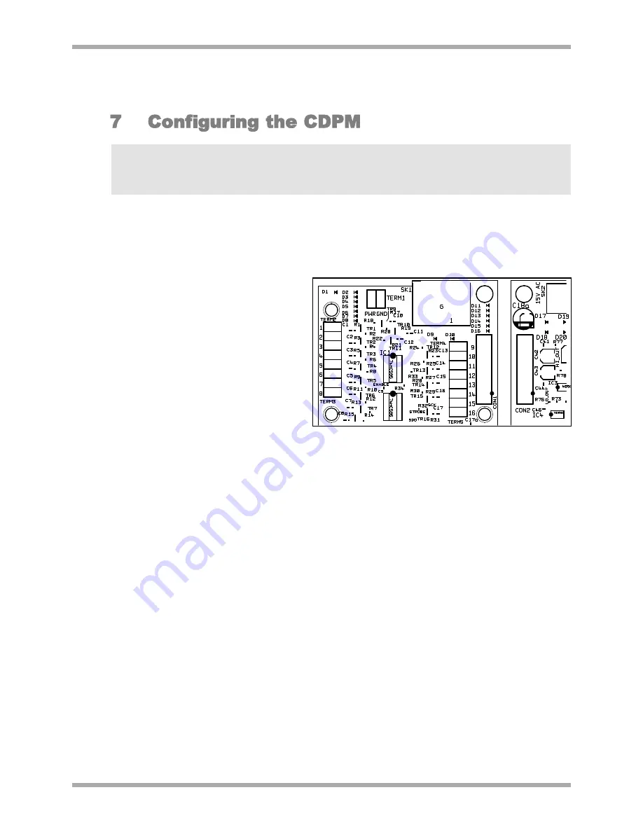
Jumper settings are only checked at initialisation of the microphone, shortly after the power has

been connected. In order for jumper changes to be recognised, the power will need to be disconnected
and then reconnected to the microphone.  See section 8 for a summary of jumper settings, their purposes
and a diagram detailing their locations.

When removing jumpers we recommend that the link remain connected to one leg of the header, to
prevent loss of the link.


A CDPM can derive power from the RJ45 connections, an external power supply or from the
analogue module PWR terminal.
Powering from the RJ45
connections is only an option for the
microphone closest to the mixer.

To power a CDPM from the
short-to-ground access contacts of
a Cloud mixer, the +V connection
from the mixer should be connected
to the PWR screw terminal on the
optional analogue module.  If a +V
terminal is not available on the
mixer, then an external power
supply will have to be used
(see Section 4).


It is possible to offset the zones a microphone is mapped to by setting the display.  This is useful
in situations where a CDPM is to operate over a sub-set of the available zones.  Factory default
is for the display to be set so that Zone 1 on the CDPM display corresponds to Zone 1 on the
paging network.  Jumpers J11-14 offset the display such that the displayed zone on the CDPM
corresponds to the network zone which is the sum of the display and the offset.   When each of
these jumpers is in the ‘ON’ (linking the pins) position they will add the following amounts to the
display offset:

J11 = +8
J12 = +4
J13 = +2
J14 = +1

E.G.  To set a CDPM-4 to operate on zones 10-13, links should be on for J11 and J14.  J12 and
J13 should be unlinked.  Zones 1-4 on the CDPM display will then correspond to network zones
10-13 respectively.

In any given installation, the CDPM network will support a maximum of 16 zones.  If a CDPM
display is set such that it accesses network zones greater than 16, these zones will wrap back
around to zone 1 upwards.

E.G.  If a CDPM-8 display is set to operate from zone 10 (J11 on and J14 on) then buttons 1-7
will correspond to zones 10-16 and button 8 on the microphone display will correspond to
zone 1.

6

V1 210605

Fig 7.1: PWR terminal location

Summary of Contents for CDPM

Page 1: ...Version 1 CDPM Setup and Installation Guide CDPM DIGITAL PAGING MICROPHONE Cloud Electronics Limited Copyright Cloud Electronics Limited 2005 Clearly Better Sound...

Page 2: ......

Page 3: ...CS LIMITED CDPM Setup and Installation Guide Cloud Electronics Limited 140 Staniforth Road Sheffield S9 3HF England Phone 44 0 114 244 7051 Fax 44 0 114 242 5462 E mail technical cloud co uk WebSite w...

Page 4: ......

Page 5: ...ments 2 4 1 Using an External Adapter 2 4 2 Powering from a Cloud host mixer 3 5 Cables and Connections 3 5 1 Connecting between CDPM microphones 3 5 2 Connecting the CDPM to a mixer using RJ45 4 5 3...

Page 6: ...lation Guide 7 8 Enabling Disabling Zone Buttons 8 7 9 Terminating the Buss 9 7 10 Configuring dual purpose microphone inputs on the Host Mixer 9 8 Jumper and default settings summary 10 9 Scenarios 1...

Page 7: ...rable two layer announcement priority system auto zone reset after announcement and zone disable The different models of CDPM microphone accommodate 4 8 12 and 16 zones respectively Sixteen is the max...

Page 8: ...continue to its conclusion The interrupting CDPM will flash its selected zone LEDs to indicate that the announcement cannot be made and that the system is already in use The zone selection on the mic...

Page 9: ...r the custom interface the CDPM microphones use to communicate Audio is directional on this interface and so is transmitted from the OUT connection to the IN connection on the next microphone or mixer...

Page 10: ...Cable The audio cable should be a standard two core screened microphone audio cable This cable is connected to the XLR socket marked AUDIO OUT on the rear panel Connections to this XLR are pin 2 as in...

Page 11: ...al of the shaft 12 Put the cable through the threaded shaft and then insert the rubber tube Tighten the domed nut to clamp down on the cable 13 Connect access cores to their respective access terminal...

Page 12: ...tion 4 It is possible to offset the zones a microphone is mapped to by setting the display This is useful in situations where a CDPM is to operate over a sub set of the available zones Factory default...

Page 13: ...and stored in memory linking the pins on internal jumper J9 will lock these group settings to prevent groups being set during operation J9 Locks the groups NOTE J7 non volatile memory reset takes pre...

Page 14: ...led Zones can only be disabled when the unit has powered up after a NVM Reset see section 7 4 To disable a sub set of zones 1 Power up the unit on a NVM reset J7 linking pins 2 Depress and hold the cl...

Page 15: ...or as a paging microphone In order for the microphone input to be used as a paging microphone the access contacts on the rear panel should be enabled using the appropriate jumpers The table below sho...

Page 16: ...will mean removing the connection to that unit For access terminal block connections this is best achieved at the mixer end of the connection Only reassemble the unit using the original screws or scre...

Page 17: ...s a dual purpose input Since there is only a single microphone this unit can be powered from the mixer connections a CDPM PSU will not be required Since the installation is small there is no requireme...

Page 18: ...a separate set of audio sources to the rest of the hotel so a Z4II four zone mixer is allocated for the Gym facilities The remaining 7 zones are to be distributed through a Z8II eight zone mixer The...

Page 19: ...12 are to be disabled for the Gym microphone button 4 is to be disabled In this same initialisation stage the CDPM 12 groups can be set These are set by selecting the required zones on the display and...

Page 20: ...All that now remains is for the microphones to be physically installed and connected as required Fig 9 2 1 Access Contact Connections between PP3 PP4 and mixers CLOUD ELECTRONICS LTD 140 STANIFORTH R...

Page 21: ......

Reviews: