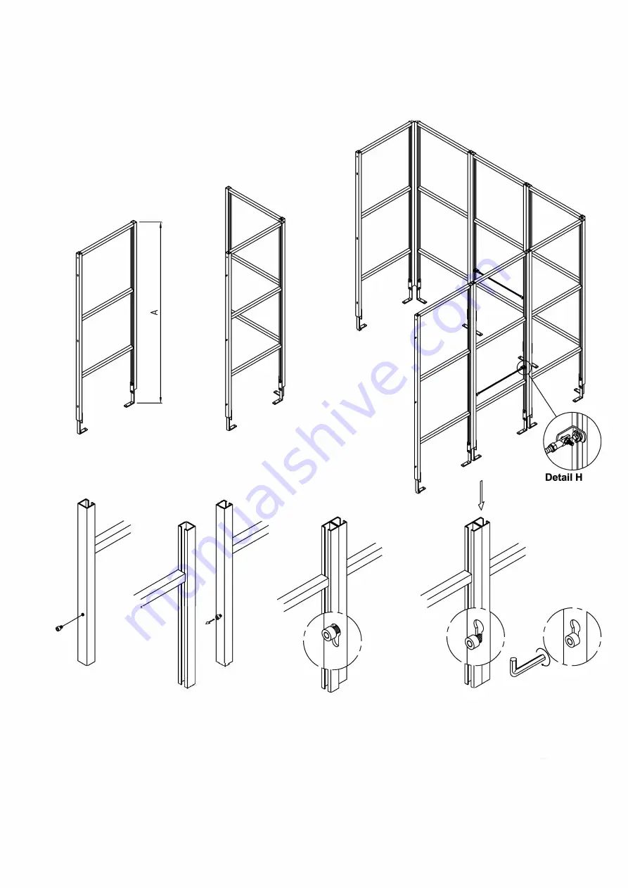
3 Basis
3.1 U-setup for the frames
(Cabin model 4 serves as example)
Figure 3a
Height adjustment
Figure 4
0
Connecting the frame parts
Figure 3b
Corner
Figure 3c
Clamping
device
3)
First adjust all frames to the desired height using the adjustable legs A (fig. 3a.). A=1900mm (=minimum height) or
2000mm (=maximum height) and turn the legs tight using the clamping bolts. Form a Li-setup by first forming a right
angle with two frames and 3 corner pieces (fig. 3b) and continue assembling anticlockwise (fig. 3c).
A chalk line made on the floor with a chalk box on one long side of the cabin is a good aid for aligning the frame
parts. This line serves as a reference for the assembly of the cabin frame. The frames are fixed together using
M8x12 hexagon socket bolts (fig. 4) and the corner pieces. Use a frame fitted with clamping device where a seat
element must be fixed. See detail H. Note: Fit frame parts in such a way that the upper surfaces are level.
The size of the setup and the positions of the different parts depend on the cabin model to be built.
(in this case model 4)
SEDNA LINE 2008/05
9


