PULSAR
®
PLUS 55-S SUCTION BLAST CABINET
Page 16
© 2021 CLEMCO INDUSTRIES CORP.
www.clemcoindustries.com
Manual No. 30423
5.5.2
Using a manometer (as noted in Section 5.10
and listed in Section 10.1) is the most accurate method of
monitoring and adjusting cabinet pressure. Following the
instructions packed with the manometer, start the exhauster,
insert the needle into a glove, and adjust pressure using
the inlet damper. Open the damper further to decrease
static pressure or close it further to increase pressure.
5.5.3
If a manometer is not available, use the gloves
as an indicator. With the exhauster ON, the gloves
should be inflated, but not elevated off the grate.
5.6
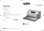
Door Interlocks ‒ Figure 17
Never bypass the door interlock system. Doing
so can result in serious injury from unexpected
blasting.
5.6.1
The door interlocks disable blasting when doors
are open. To enable blasting, the door-interlock switches
must be engaged when the doors are closed. The
interlocks are set at the factory and do not normally
require field adjustment unless parts are replaced. When
adjustment is required, proceed as follows:
5.6.2
Close cabinet doors.
Figure 17
5.6.3
Loosen the actuator-bracket screws and
adjusting-screw nut. Move the actuator bracket up or
down, and the adjusting screw sideways, as needed to
center the adjusting screw on the switch’s button (in
center of detent sleeve). Tighten the bracket screws.
5.6.4
Turn the adjusting screw out until it no longer
contacts the switch’s button.
5.6.5
Turn the screw in until it engages the switch
without applying excessive pressure. Listen closely and
a click can be heard as the screw engages and
disengages the switch. Tighten the adjusting screw nuts.
5.6.6
Test the operation with the doors open and then
again closed. Negative pressure inside the cabinet may
cause the doors to flex inward. Tests should be
performed with the exhauster running. Point the nozzle
away from the door during the tests and open the door
only enough to disengage the interlock switch. The
interlocks should stop the blasting when either door is
open and permit blasting when the doors are closed.
5.7
Dustbin Interlock – Figure 18
5.7.1
The dustbin interlock switch disables blasting
when the dustbin is lowered to remove it from under the
dust collector.
5.7.2
To enable blasting, the interlock switch must be
engaged when the bin is closed (raised against the dust-
collector hopper), as shown in the Detail 1 Circle in
Figure 18. The interlock is set at the factory and does
not normally require field adjustment unless parts are
replaced. When adjustment is required, proceed as
follows:
5.7.3
To disable blasting and permit removal of the
dustbin, the top of the bin must clear the switch, as
shown in the Detail 2 Circle in Figure 18.
5.7.4
To adjust the switch:
5.7.4.1
Pull the latch handles down to lower the bin.
5.7.4.2
Loosen the switch’s mounting nuts. Move the
switch up or down as necessary to obtain approximately
1/4" between the bottom of the hopper flange and
bottom of the switch’s plunger, as shown in the Detail 3
Circle in Figure 18.
5.7.4.3
Tighten the screw to secure the switch and
maintain the adjustment.
Cabinet Door
Detent Sleeve
Loosen nut and move adjusting
screw sideways to center the
screw on the over-travel stop.
Adjusting-Screw Nut
Loosen the bracket screws, and
move the bracket up or down to
center the adjusting screw on the
valve-switch button.
Actuator Adjusting Bracket
Bracket Screws
Adjust the screw to push the
valve-switch button in when
door is closed.
Adjusting Screw
Interlock-Switch Button