CCT CLIMATE CONTROL TUBE
Page 5
© 2007 CLEMCO INDUSTRIES CORP.
•
www.clemcoindustries.com
•
Manual No. 08850
3.2
Air Supply and Pressure
3.2.1
Initiate the air supply and regulate air pressure
between 90 and 100 psi, as shown in Section 2.4.3.
3.3
After donning the respirator, securely attach the
belt and climate control tube around the waist. Adjust the
belt size as required.
3.4
Adjust Air Temperature
3.4.1
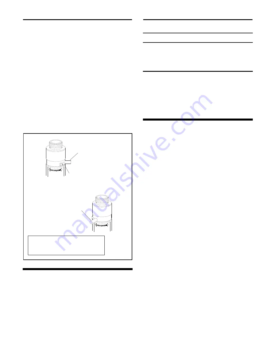
To adjust air temperature, move the temperature
control lever (shown in Figure 3) fully toward the right,
lighter end of the indicator arrow, for maximum, or fully left,
darker end of the arrow for maximum warming. Position
the lever anyplace in between to attain the most
comfortable temperature setting.
WARMER - COOLER
WARMER - COOLER
Figure
3
4.0 PREVENTIVE
MAINTENANCE
4.1 Air
Filter
Screen
4.1.1
Inspect and clean the air filter screen monthly. If
inadequate air flow is experienced, stop using the
climate control tube and inspect the screen for blockage.
CAUTION
Debris or abrasion on the screen is one
indication of dirty air. Dirty air will cause rapid
erosion of critical parts of the climate control
tube, which will decrease efficiency and life of
the control tube.
4.1.2
To clean the air filter screen, unscrew the quick
disconnect nipple from the inlet elbow. Turn the elbow
upside down and tap it on a solid surface to remove
loose debris. The screen can be removed by tapping the
elbow described above. If the screen is wedged in place
it may be necessary to destroy it in order to remove.
Replace the screen before reassembly.
5.0 SERVICE
MAINTENANCE
5.1
Service maintenance is divided into two stages.
The first stage is to replace leaking seals and to clean the
top end when the unit is otherwise working properly. (A
small leak from around the temperature control lever is
normal, and should be the same temperature as the
expelled air.) The second stage is to service and clean the
body and tube assembly. This is usually required when the
tube loses efficiency.
NOTE: Have a 08845 seal kit on hand before servicing
either stage. Clean all parts with mild soap and water,
rinse thoroughly, and dry.
5.2 First
Stage Service, Refer To Figure 4
5.2.1
Remove belt bracket, lower screw, and inlet
elbow.
5.2.2
Remove the temperature control lever and set
screw stop from upper valve plate. Make a note of the
location of each before disassembly.
5.2.3
While applying pressure on the outlet connector,
remove the second retaining screw (the first was removed
with the bracket in paragraph 5.2.1) and remove the
connector from the housing. Remove the o-ring from the
connector.
5.2.4
Remove the spring and spring support washer.
5.2.5
Remove the o-ring and upper valve plate.
5.2.6
Remove the o-ring from lower valve plate.
NOTE: If the lower plate and pin come loose, refer to
Figure 4 for reassembly.
Temperature
Control Lever
Move the control lever fully
left for maximum warming
Temperature
Control Lever
Move the control lever fully
Right for maximum cooling
Position the lever anyplace between
warm and cool to attain the most
comfortable temperature setting
Exhaust port
Warm air exhaust from this port
when the lever is in the cool mode.
Cool air exhaust in the warm mode.


