background image

ClearCube Technology, Inc.        1505 Volta Dr.  Suite 100     Cedar Park , TX  78641        (512) 652-3500      www.clearcube.com

Power management 

Storage drives and carrier 

Power on and 

power off

The power button is located on the top portion of the front panel, shown as 1 in 

Figure 1

 on 

page 1

Power on:

 After inserting a blade in a chassis or connecting power for configuration outside of a 

chassis, press the 

power button 

to power on the blade. 

Result:

 The blade powers on and the power indicator (1) is illuminated. 

Power off:

 Press and hold the 

power button

 for about 3 seconds to power off a blade. 

Result:

 The blade powers off and the power indicator (1) turns off.

Reset power

The reset button is located on the bottom portion of the front panel, shown as 2 in 

Figure 1

 on 

page 1

When a blade is powered on, press the 

reset button

 to reset power. 

Result:

 The blade powers down, the power indicator (1) turns off, and the blade powers on again.

About blade 

storage drives

A6108 blades use carrier free hot swappable bays for drives—such as hard disk drives (HDD), solid 

state drives (SSD), self-encrypting drives (SED), and hybrid drives (SSHD). 

NOTE: 

A6018 blades does support hot-swap replacement of drives. When hot swapping hard drives, 

make certain that the OS drive is not removed.. 

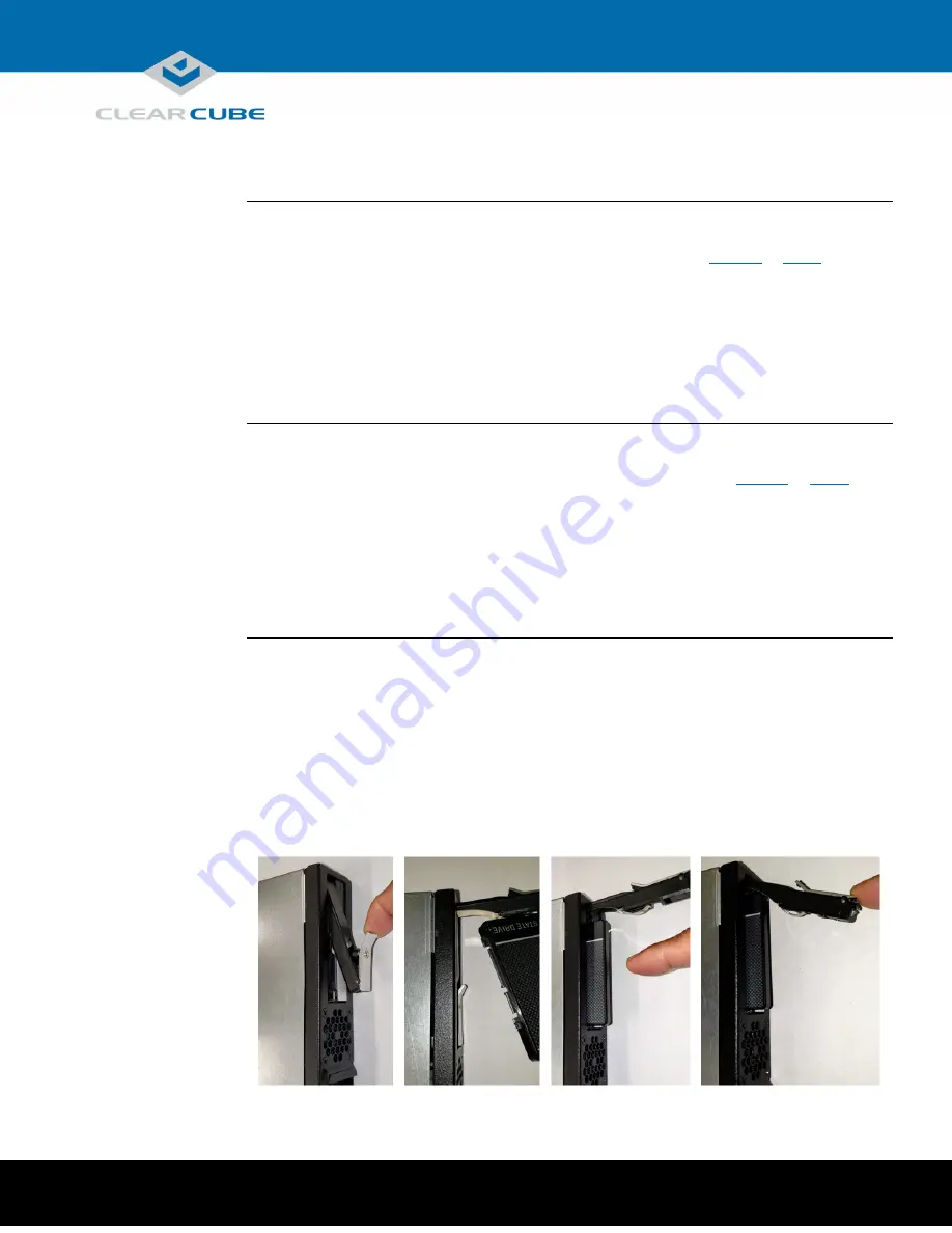
Storage drives do not require power cables or data cables when inserting in bays. Power and data 

connectors are housed inside the blade—insert and fully seat the carrier and fasten with screws. 

The picture below shows the storage drive carrier. 


Page   of   

P/N <TBD> Rev A, 1.0.10.9.2020


3

15

Summary of Contents for A6108

Page 1: ...is illuminated solid when power is on Button blinks slowly to indicate blade is in Sleep power state 2 Reset button and HDD indicator Button Press to reset blade power Indicator Button flashes to indicate hard drive activity 3 USB Dual USB 2 0 port 4 Video Access and Pull TabProvides access to select video and pull tab for removal from chassis 5 Storage drive carrier Holds up to two storage drives...

Page 2: ...tel AMT and provides references to additional information about Aseries blades A series chassis and to information about using PCoIP technology A6108 overview A6108 blades are 6U high single slot blades that mount in an A3100 chassis The A3100 chassis provides power network interfaces and a USB port for each blade The picture below shows zero clients connected to A6108 series blades in an A3100 ch...

Page 3: ...utton is located on the bottom portion of the front panel shown as 2 in Figure 1 on page 1 When a blade is powered on press the reset button to reset power Result The blade powers down the power indicator 1 turns off and the blade powers on again About blade storage drives A6108 blades use carrier free hot swappable bays for drives such as hard disk drives HDD solid state drives SSD self encryptin...

Page 4: ...ClearCube Technology Inc 1505 Volta Dr Suite 100 Cedar Park TX 78641 512 652 3500 www clearcube com Continued on next page Page of P N TBD Rev A 1 0 10 9 2020 4 15 ...

Page 5: ...rk TX 78641 512 652 3500 www clearcube com Storage drives and carrier Continued Drive order The picture below shows how storage drives are ordered in the storage drive carrier 3 Drive order in the storage drive carrier Page of P N TBD Rev A 1 0 10 9 2020 5 15 ...

Page 6: ... From the top pull the bezel toward you and lift up to remove it 3 Hold the blade so the D shaped handle in the front of the blade is upright and is facing you Align the blade with the top and bottom guides in the chassis and slowly insert the blade Result When fully seated the blade is flush with the front edge of the bottom guide bracket NOTE There is slight resistance when blade connectors are ...

Page 7: ...in specified below for more information Set mass storage lockout on PCoIP host cards which enables you to prohibit or restrict the use of USB based mass storage devices such as flash drives on ClearCube blades Expansion Backplane As noted above the A3100 chassis provides power network and USB connections for A6108 blades The picture below shows the network connections on A3100 Chassis Expansion Ba...

Page 8: ...ClearCube Technology Inc 1505 Volta Dr Suite 100 Cedar Park TX 78641 512 652 3500 www clearcube com Page of P N TBD Rev A 1 0 10 9 2020 8 15 ...

Page 9: ...onfiguring an A6108 blade outside of a chassis From inside a chassis make sure all network and power cables are attached to the chassis Before you begin be sure to have Ethernet cables a standard 120 V computer power cable IEC 60320 C13 connector with NEMA 5 15 inlet a DisplayPort monitor video cables and power cables a USB keyboard and a mouse and NOTE These instructions assume devices are connec...

Page 10: ...ing network If you are imaging from an imaging network connect an Ethernet cable to the standard Ethernet port on the rear of the blade this is the bottom most port when the blade is resting on a table as shown below Connect the other end of the cable to a switch connected to an imaging network 5 Network ports on the rear of the blade 5 Connect a power cable to the power connector at the rear of t...

Page 11: ... boot logo select the choice needed DEL or F2 to enter BIOS Setup F7 to enter boot menu Next steps You can now deploy the A6108 blade See the sections below for important details about A6108 configuration operation and maintenance Flashing the motherboard BIOS The A6108 BIOS is available from the ClearCube Support site The BIOS download includes detailed instructions about how to flash the motherb...

Page 12: ...owser based utility VNC Viewer Plus and Spiceworks Be sure to choose a console that supports your management objectives Network The A3100 chassis supports Intel AMT through the primary Ethernet port only See Figure 5 and Figure 6 above for more information Supported features A6108 blades support all Intel AMT features except for KVM over IP Default login credentials The list below shows default In...

Page 13: ...ClearCube Technology Inc 1505 Volta Dr Suite 100 Cedar Park TX 78641 512 652 3500 www clearcube com Continued on next page Page of P N TBD Rev A 1 0 10 9 2020 13 15 ...

Page 14: ...onnect to a blade Perform these steps on each blade you will manage from an AMT management console Step Action 1 Log in to the AMT BIOS extension as shown in the section above 2 Select Intel R Standard Manageability Configuration and press ENTER 3 Select Activate Network Access and press ENTER Result A message is displayed Press Y on your keyboard 4 Press ESC to return to the main menu 5 Select ME...

Page 15: ...em User s Guide All documentation is located at http www clearcube com support Contacting Support Web www clearcube com support Email support clearcube com Toll free 866 652 3400 Direct 512 652 3400 Page of P N TBD Rev A 1 0 10 9 2020 15 15 WEEE Disposal Guidelines In the European Union this electronic product falls under the European DirecCve 2002 96 EC WEEE When it reaches the end of its useful ...

Reviews: