


Quantum DXi4700 Installation Guide
January 2018
6-68551-02
Contents
Preparing for the Installation
Installing Components in the
DXi4700 Node
Installing the DXi4700 System
in the Rack
DAE/Veeam Memory Module
Installation
This guide provides hardware installation and initial system
configuration instructions for the Quantum DXi4700 disk backup
system. For more information, see the
Quantum DXi4700 User's
Guide
.
Make sure to take the online training for the DXi4700 in order to make
the best use of your product. The online training is available at:
The
DXi4700 Installation & Configuration
video is available at
.
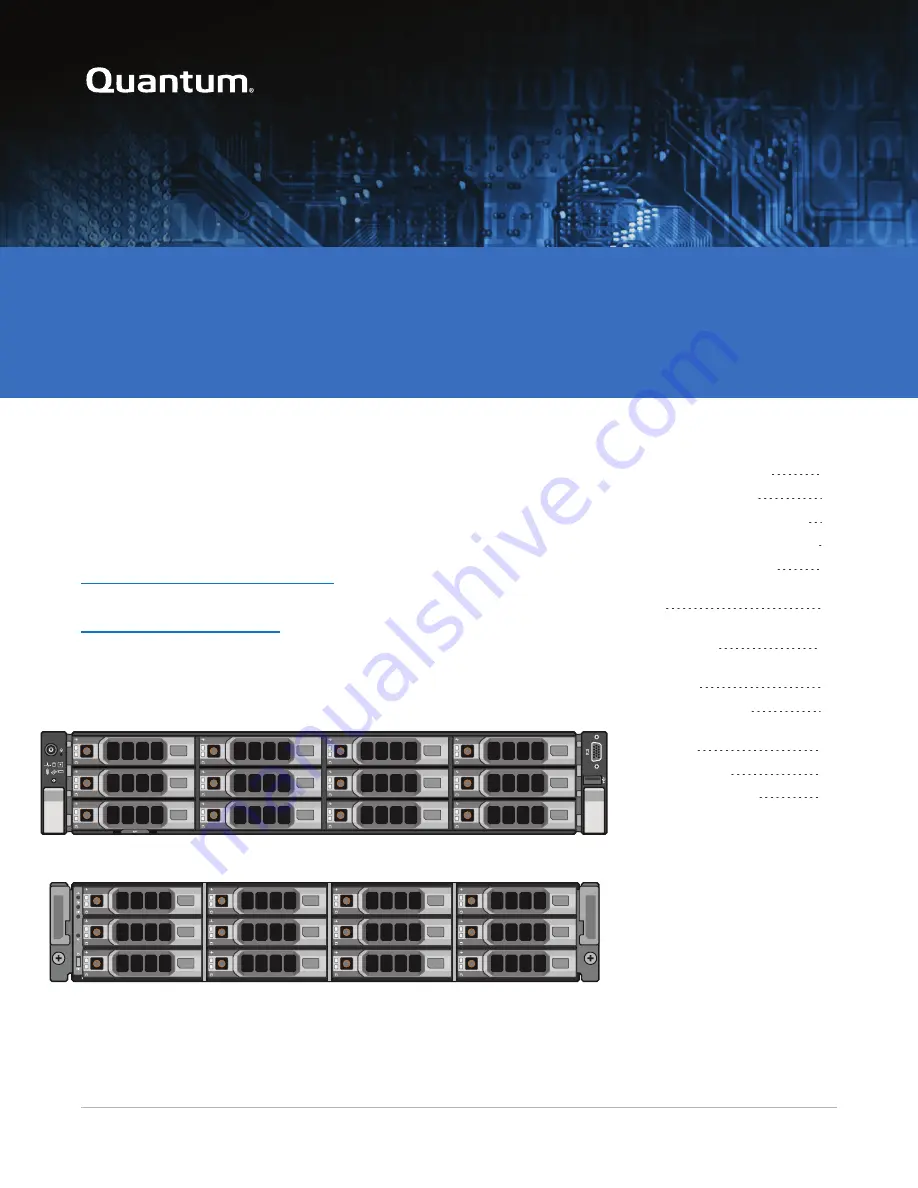
DXi4700 Node
DXi4700 Expansion Module (JBOD)


