background image

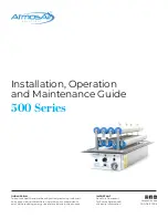
Installation, Operation & Maintenance Guide


500 Series 

7

1-888-MY-AIR11        CAG-06-21-003        AtmosAir.com

Mechanical Installation — Mounting Continued

Installation Orientation

Cut-Out Dimensions (mm/in)

Model

A

B

500EC

495.3mm (19.5”)

228.6mm (9”)

500FC

660.4mm (26”)

228.6mm (9”)

508FC

660.4mm (26”)

228.6mm (9”)

Electrical Installation

AtmosAir 500 series systems require an average of 50 watts 
per unit. A replaceable T 500mA, slow-blow 5mm x 20mm 
fuse protects the unit.

Follow proper electrical procedures, guidelines, and codes 
for providing power supplies to the systems,

 including 

requirements for conduit, sufficient ampacity, phase 

balancing, etc. Electrical installation should be performed by a 

qualified electrician.

1. 

Field-install a junction box within 2.44 meters (8’) of the 
unit(s). Each 500 series unit is typically shipped with a 10-

foot power lead in a flexible metallic conduit with a quick-

connect power plug on one end and bare wires on the other.

!!!WARNING!!!

The secondary voltage to the ionization tubes can be as high as 3000 volts AC. Do NOT connect to power before the installation is complete and all 

personnel are aware of imminent operation. Always disconnect power to the unit before handling any of the components.

2. 

The unit is equipped with a normally open relay that closes 
on ionization start-up and opens on loss of power. This relay 
can initiate a local alarm or be tied into a building automation 
system. Connection is via a DB-9 connector. Pins 1 and 5, 
starting from the top left, are the active pins. There is no 
electrical power across the terminals.

Preferred

Airflow

DB-9 Connector

Inactive Pins
Active Pins

Duct Wall

Acceptable

A

B

Summary of Contents for AtmosAir 500 Series

Page 1: ...ove health and wellness by actively restoring indoor air to its pure natural state where no pollution or contaminants exist while reducing energy use and emissions in the process AtmosAir com CAG 06 21 003 IMPORTANT Save this Document for Future Reference Warranty Information ...

Page 2: ...the unit before handling any of the components DO NOT connect to the power before the installation is complete and personnel are aware of the imminent operation Secondary voltage to the ionization tube can be as high as 3000 Volts AC Carefully read this instruction booklet before beginning the installation Follow each installation or repair step exactly as shown and explained in this guide Observe...

Page 3: ...RVIEW 4 Control Panel Diagram 4 02 INSTALLATION 5 Mechanical Installation 5 Mechanical Installation Mounting 6 Mechanical Installation Mounting Continued 7 Electrical Installation 7 03 FIELD WIRING DIAGRAM 8 04 OPERATION 9 05 MAINTENANCE REQUIREMENTS 9 06 TROUBLESHOOTING 10 07 EXPLANATION OF TECHNOLOGY 11 08 PRODUCT WARRANTY 12 ...

Page 4: ...require inspection and maintenance 1 AtmosAir 500 series ionization generator 2 Ionization tubes Because there are no moving parts the systems have very low failure rates and minimal maintenance requirements For more information read the AtmosAir 500 series submittal documents Control Panel Diagram AtmosAir 500 Series Control Panel Layout Unit Size Flowrate CFM Drag mm inch WG Pascals 500EC 8 000 ...

Page 5: ...ey have been packaged separately install the ionization tubes using the supplied friction nuts and clamp screws Gently tighten the tube grounding clamps to ensure solid contact with the tube s outer mesh Do not over tighten either connection In most cases units come with tubes pre installed 3 Orientation Install the unit with tubes parallel to the airflow and the nosecones normal to the airflow wh...

Page 6: ...llation Min Distance 6in 101 6mm for Continuous Installation Min Distance 6in 152 5mm Typical 500 Series Footprint NOTE Watch for support structures Turning Vanes Acceptable Unacceptable Preferred Air Flow Air Flow Duct Section View Multiple Unit Installation Multiple Unit Installation Mechanical Installation Mounting Installation Operation Maintenance Guide 500 Series 6 1 888 MY AIR11 CAG 06 21 0...

Page 7: ...nction box within 2 44 meters 8 of the unit s Each 500 series unit is typically shipped with a 10 foot power lead in a flexible metallic conduit with a quick connect power plug on one end and bare wires on the other WARNING The secondary voltage to the ionization tubes can be as high as 3000 volts AC Do NOT connect to power before the installation is complete and all personnel are aware of imminen...

Page 8: ...LD WIRING DIAGRAM 500 SERIES TO AFS 262 AIRSWITCH SHEET 1 OF 1 UNLESS OTHERWISE SPECIFIED SCALE 1 3 REV B DWG NO A SIZE TITLE NAME DATE COMMENTS FIELD WIRING DIAGRAM FOR CONNECTING 500 SERIES TO AFS 262 AIR SWITCH TO LINE VOLTAGE Q A REV B SB 2 22 21 ENG APPR TA 2 21 19 2 21 19 DRAWN HRG 2 21 19 FINISH MATERIAL INTERPRET GEOMETRIC TOLERANCING PER DIMENSIONS ARE IN INCHES TOLERANCES FRACTIONAL 010 ...

Page 9: ...e mains power before performing maintenance or troubleshooting the system Optional Check performance using a high voltage probe minimum of 5000 V Contact AtmosAir for additional minimum probe specifications paired with a multimeter Follow proper safety procedures for dealing with high voltages If you are uncertain do NOT perform any maintenance with the power on and instead proceed to the next ste...

Page 10: ...other degeneration of the tube material that may cause the tube to become breached and fail and short circuiting to occur 7 If physical inspection has not revealed the cause of failure one may carefully observe the tubes as the ionization system is turned on to determine whether short circuiting is occurring at a particular tube The fuse will usually blow again but for a short time one may observe...

Page 11: ...ntain elevations AtmosAir s unique and proven air purification process significantly reduces mold montrols the spread of bacteria and airborne viruses and reduces airborne particles that evade normal filtration solutions AtmosAir equipment uses non thermal plasma technologies to generate bi polar Ionization that attacks and breaks down odors and contaminants 07 EXPLANATION OF TECHNOLOGY 07 EXPLANA...

Page 12: ...IONS OF CLEAN AIR GROUP HERIN ARE EXPRESSLY GRANTED IN LIEU OF ALL WARRANTS WHETHER EXPRESS OR IMPLIED INCLUDING BUT NOT LIMITED TO IMPLIED WARRANTIES OF MERCHANTABILITY AND FITNESS FOR A PARTICULAR PURPOSE ALL IMPLIED WARRANTIES INCLUDING WARRANTIES OF MERCHANTABILITY AND FITNESS FOR PARTICULAR PURPOSE ARE LIMITED TO THE TERM OF THE EXPRESS WARRANTY GRANTED HEREIN Some states do not allow limitat...

Reviews: