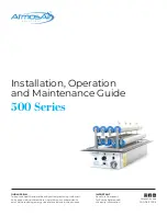
Installation, Operation & Maintenance Guide
500 Series
5
1-888-MY-AIR11 CAG-06-21-003 AtmosAir.com
500
Series
Inside
500
Series
Inside
500
Series
Inside
500
Series
Inside
02
INSTALLATION
The AtmosAir 500 series equipment can be mounted on the
side of a duct or air handler wall, using the integral mounting
flange and a weather-strip gasket, or inside an air handler
using a custom mounting rack with an optional wall mount
bracket. In an air handler, the units operate best when located
after the filters. Ideally, the tubes lie parallel to the direction of
airflow with the end of the tubes pointing upstream.
When installed on the side of a duct or air handler wall, the
outer box and faceplate should not be exposed to direct
sunlight or moisture. If installing outside, a weatherproof
enclosure with an access panel for servicing should be
installed over the AtmosAir Ion Generator (which can be
provided by AtmosAir).
The 500 series operates on 110 VAC, 50/60 Hz or 250 VAC,
50/60 Hz is available upon request. If using the integral
remote monitoring panel, the connection is made using a
supplied 9-pin (DB-9) connector. The tubes and electrode
contacts should not come into contact with any conductive
surface. A minimum 101.6mm (4”) clearance around the tubes
is recommended.
Mechanical Installation
1.
Carefully remove the equipment from its shipping
container. Inspect the box, components, and tubes for
damage. Verify that the unit’s voltage rating is the same as
the available voltage, either 110 VAC, 50/60 Hz or 250 VAC,
50/60 Hz.
2.
If they have been packaged separately, install the
ionization tubes using the supplied friction nuts and
clamp screws. Gently tighten the tube grounding clamps
to ensure solid contact with the tube’s outer mesh. Do not
over-tighten either connection! In most cases, units come
with tubes pre-installed.
3. Orientation:
Install the unit with tubes parallel to
the airflow and the nosecones normal to the airflow,
whenever possible; otherwise, perpendicular orientation is
acceptable. If multiple units are installed in the same duct,
stagger the units, if possible, in the airflow so they are not
in the same airflow path.
4. For in-duct installation:
Verify the flange gasket are in
place and in good shape to ensure the unit seals properly.
Make a cut-out in the duct sized per the illustration and
table on the following page. Use the unit as a template for
the mounting screw locations. Affix the unit securely in
the duct using self-tapping screws.
Do not over-tighten,
this may strip the screw-hole.
The unit is self-sealing to
the duct, so no further sealing is needed.
5. For in-plenum/AHU installation:
Mounting varies with
rack-style. Follow mounting instructions provided with
rack. Typically, racks require 101.6mm (4”) of clearance from
walls.
6.
Units should be installed to allow easy access for
maintenance. Install units so that the power switch and
5-step power adjustment knob are accessible. When
oriented vertically, control panel should be upwards.
Types of Insulated Duct Walls
A
B
C
D
A.
Single Wall, No Insulation
B.
Single Wall, Internal Insulation
C.
Single Wall, External Insulation
D.
Double Wall, Internal Insulation
Duct Wall
Duct Wall
Duct Wall
Duct Wall
Fiberglass
Insulation
Fiberglass
Insulation
Cut Away
Double Wall
External
Insulation


