2.
Thoroughly clean all machined surfaces to remove any protective coating
that may be present. The surfaces should then be lightly oiled.
3.
Gently, and with assistance, turn the bed assembly over so that it is resting on
the headstock and tailstock, and to protect those components, rest them on
suitable pieces of packing material. Ensure the unit is completely stable,
adjusting the packing pieces as necessary until it is.
4.
Bolt on the two bed mounting plates (item 54B), ensuring they are the right
way round, i.e. the open sections facing each other.
Secure each plate using four M8 Allen screws with washers supplied, ensuring
the
35mm
screws are used at the
HEADSTOCK
end, and the
45mm
screws at
the
TAILSTOCK
end.
5.
Bolt the four Legs (item 54A) on to the Bed Mounting Plates (item 54B), using
the 12 Carriage Bolts supplied. Ensure that the legs are on the outside of the
mounting plates, and the bolt heads are on the outside of each leg, firmly
located into the square holes in the leg, and the flat washers are in place
against the inside of the bed mounting plate.
LEAVE NUTS FINGER TIGHT ONLY.
6.
Bolt on the two Long Cross Members (item 54C), and two Short Cross Members
(item 54D), to the insides of the legs ensuring they are the right way round, (i.e.
the broad flat angle sections are facing the bed).
DO NOT fully tighten the nuts. First rock the leg assembly to ensure there are no
distortions or that no component is under stress. When satisfied fully tighten all
nuts and bolts so far assembled.
7.
Should you wish the Bed Extension (item 52), to be a permanent feature, it is
best to bolt it on at this stage. Turn it so that the machined bed side is face
down. Offer it up to the lathe bed at the headstock end, with the mounting
holes facing the lathe bed. Rest the extension on a piece of packing material,
if necessary, whilst lining up the holes in the end of the lathe bed with those in
the extension. Insert the two 10mm Allen screws with spring washers provided,
and tighten them fully.
8.
With assistance, lift and turn the complete assembly on to its legs.
9.
Attach the Headstock Clamping Handle (item 24A), to its spigot ensuring the
spring and screw are correctly positioned. (See parts diagram)
Your Wood Lathe is now fully assembled, and may be prepared for use.
9
D. For Turning Between Centres
For turning between centres, two hardened Morse Taper centres are provided.
The Live Centre should be gently tapped into the work (at its exact centre -
previously marked out), using a wooden mallet, and then mounted in the
Headstock Spindle with work attached (refer to ‘The Headstock’ section for
information on mounting the centre).
Move the Tailstock along the bed (with the centre in place), and lock (using
clamp - item 37), in a position where the centre is approximately 1" - 1½” from the
workpiece. Advance the Centre, by turning the feed handle (item 49) until it
makes contact with the work at its exact pre-marked centre. Continue to
advance the Centre whilst simultaneously rotating the work by hand. When it
becomes difficult to turn the work, slacken off the feed about one quarter of a
turn, and lock the Tailstock Spindle.
Note: The Tailstock centre should be lubricated (unless it is a ball bearing type),
using beeswax, tallow, or in some cases, oil - consult a wood turning manual.
E. For Faceplate Turning
Turning which cannot be worked through centres, must be mounted on a
faceplate, or other work-holding device. (Some jobs may require the use of
special chucks).
12
All face plate work is done by scraping.
Any attempt to use a cutting technique
on edge grain, will result in hogging or
gouging, which may tear the tool out
of your hands.
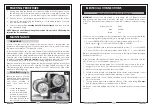
For Faceplate turning, the work (suitably
trimmed so that it is as near to its final
dimension as possible), should be firmly
mounted on to the faceplate, using
screws as appropriate (see fig 5). The
complete assembly is then screwed on
to the headstock spindle, and tightened
securely, by holding the faceplate with
a spanner, via the flats on the
faceplate boss, and turning the spindle
collar using the spanner provided.
The screws used in securing the work to the face plate, must not be of sufficient
length as to interfere with the tool at the final dimension. It may be necessary to
screw the work to a backing piece, depending upon design, or, where screws are
not permissible at all, the work may be glued to a backing piece - fitting a piece
of paper at the joint which will allow for later separation without damaging the
wood.
Fig. 5


